GE COMPANY
DIRECTION 5472001-1EN, REVISION 6OPTIMA CT680 SERIES AND OPTIMA CT670 INSTALLATION MANUAL
Chapter 2 - Power, Ground & Interconnect Cables Page 101
2 – Install Power
NOTICE Shortening power cables is not allowed. The crimping tool and ferrules are not shipped with
the system.
If longer or shorter cables are required, order the correct set.
Excess cables cannot be stored under or behind the PDU, gantry or console.
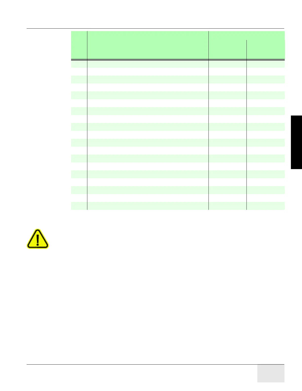
4 PDU to Room Warning Light(s) cust. supplied cust. supplied
5 PDU to Scan Room Door Switch cust. supplied cust. supplied
50 HVDC Power Cable - PDU to Gantry 2343529 2343529-2
51 HVAC Power Cable - PDU to Gantry 2343530 2343530-2
52 LVAC Power Cable - PDU to Gantry 2343528-3 2343528-4
53 LVAC Power Cable - PDU To Operator’s Console 2343531 2343531-2
54 LVAC Power Cable - Gantry to Table n/a n/a
55 Ground, PDU to Raceway 2371450 2371450-2
56 Ground, Raceway to Console 2371450-3 2371450-4
60 LVAC Power Cable - PDU to Optional UPS - -
61 LVAC Power Cable - UPS Disconnect Panel to PDU - -
90 LVAC Power Cable - PDU to PET - -
100 Signal Cable - Gantry to PDU 5419992 5419992-2
101 Signal Cable - Gantry to Console 5419981 5419981-2
102 Signal Cable (Ethernet) - Gantry to Console 5454760-2 5454760
103 Data Cable (Fiber Optic) - Gantry to Console 5478856 5478856-2
104 Signal Cable - Gantry to Table n/a n/a
110 Signal Cable - UPS Control to Room Disconnect (A1) - -
111 Signal Cable - UPS Control to UPS Disconnect Panel - -
RUN
NO. DESCRIPTION
PART NUMBER
LONG CABLES
(K
IT P/N
5444556-2)
SHORT CABLES
(K
IT P/N
5444556)
Table 2-3 System Interconnect Cables (Continued)

 Loading...


