GE COMPANY
DIRECTION 5472001-1EN, REVISION 6OPTIMA CT680 SERIES AND OPTIMA CT670 INSTALLATION MANUAL
Chapter 1 - Position Subsystems Page 47
1 – Pos. Subsystems
The gap to inspect is shown in Figure 1-14 next to the serial number.
Figure 1-14 Gantry Bearing
On most systems, a change in the bearing gap does not cause the gantry to make unusual sounds,
unless the gap is severe. If the gantry is badly damaged and the gap is severe, it can cause
operation issues. Some systems are shipped with shock indicators that must be returned to
Milwaukee.
A severe failure may be seen during installation as a problem rotating the gantry.
7.4 Procedure
1.) Remove the scan window.
2.) Remove the top cover and slide out the rear gantry cover.
3.) Slide out gantry bore cover by using the bore cover support tool (Refer to Replacement >
Gantry > Enclosure> Gantry Bore Cover Support Tool Usage in Service Method CD
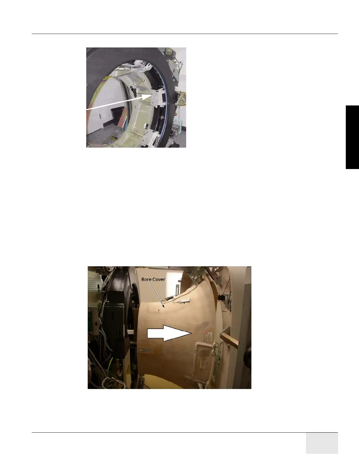
Figure 1-15 Gantry Bore Cover

 Loading...


