GE COMPANY
DIRECTION 5472001-1EN, REVISION 6OPTIMA CT680 SERIES AND OPTIMA CT670 INSTALLATION MANUAL
Chapter 2 - Power, Ground & Interconnect Cables Page 125
2 – Install Power
Section 8.0
PDU Cable Connections & Configuration
CAUTION Do not work in an energized PDU. When working on the PDU, follow this simple rule: Always
tag and lock out power to the PDU at the “main” disconnect. Failure to due so can result in
electrocution or death.
Do NOT apply power to the PDU until all work has been completed and all PDU covers are in
their proper place.
8.1 Introduction to NGPDU
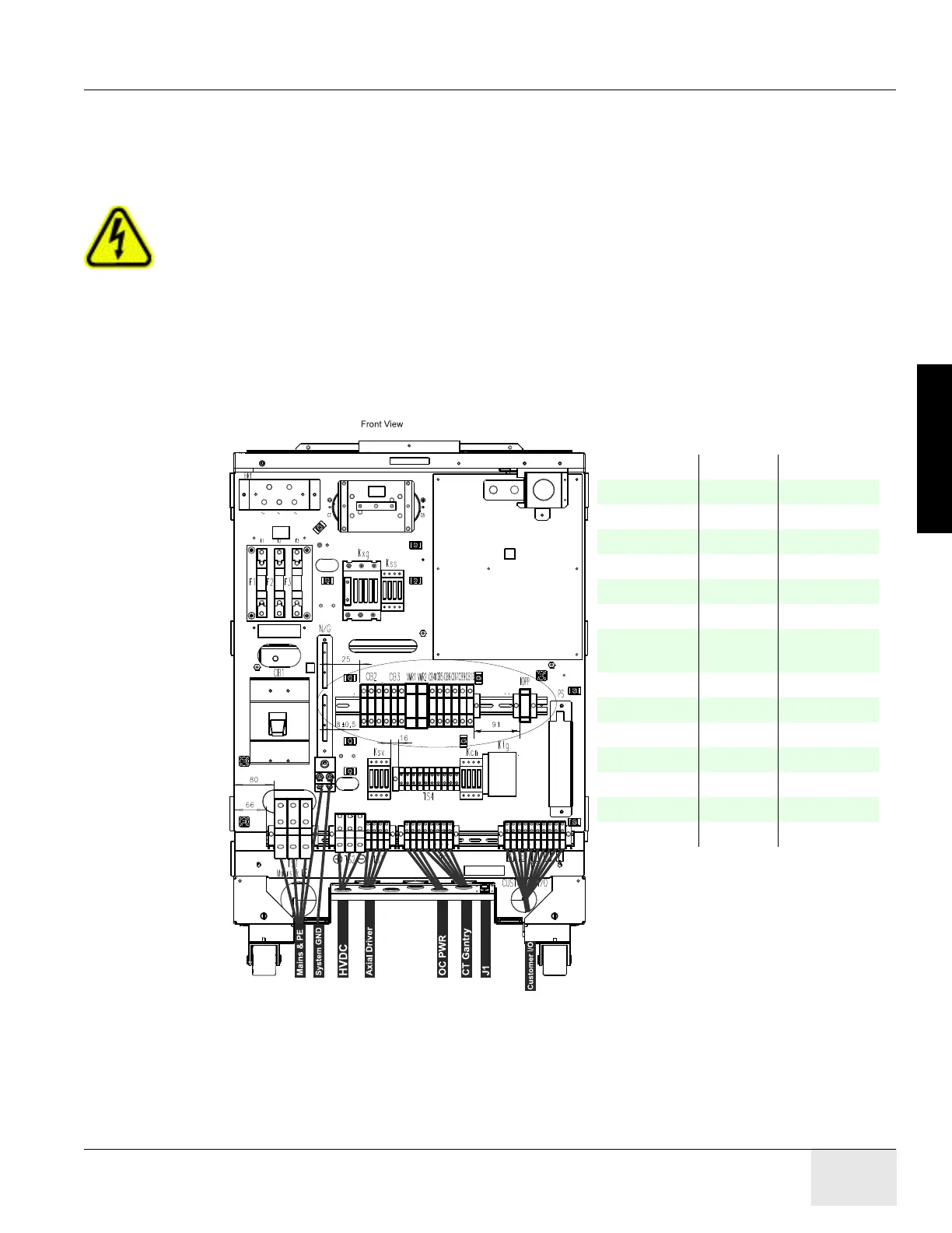
As seen in Figure 2-29, a number of cables must be installed throughout the PDU. Specific details
on each connection can be found in the sub-sections that follow. Use Figure 2-29 for reference. The
PDU has been designed to have cables routed into the PDU from behind and/or beneath it.
Figure 2-29 PDU Cable Connections - Front
Note: Wire colors may vary
HVDC TS2-1 Red
TS2-2 Grn/Yellow
TS2-3 Black
Axial TS3-1 Black
TS3-2 Red
TS3-3 Orange
TS3-4 Grn/Yellow
Console
Power
TS5-1 Brown
TS5-2 Blue
TS5-3 Grn/Yellow
CT Gantry TS5-4 Black
TS5-5 Red
TS5-6 Orange
TS5-7 Blue
TS5-8 Grn/Yellow

 Loading...


