GE COMPANY
DIRECTION 5472001-1EN, REVISION 6OPTIMA CT680 SERIES AND OPTIMA CT670 INSTALLATION MANUAL
Page 128 Section 8.0 - PDU Cable Connections & Configuration
8.1.4 440V Connection
Note: Refer to Table 2-3, System Interconnect Cables on page 100.
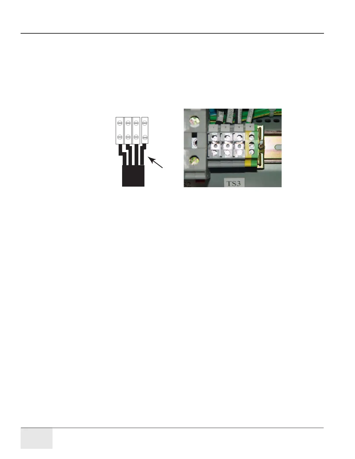
Connect the internally shielded 440V cable to TS3 on the standing panel (See Figure 2-29 for the
location of the connector and Figure 2-32 for details). Observe polarities and grounds. Do not cut
or shorten cables unless you have all of the appropriate tools and crimper to re-terminate. If short
cables are needed, have the PMI order the short cable set.
WARNING Excess cable length cannot be stored under or behind the PDU. If cables are to be stored in the
cable tray, do not overfill. Consult the local electrician to determine the maximum fill rate for your
area.
Figure 2-32 440VAC Connection
Check box when complete.
8.1.5 Gantry & Console Power Connections
Note: Refer to Table 2-3, System Interconnect Cables on page 100.
Do not cut or shorten cables unless you have all of the appropriate tools and crimper to re-
terminate. If short cables are needed, have the PMI order the short cable set.
WARNING Excess cable length cannot be stored under or behind the PDU. If cables are to be stored in the
cable tray, do not overfill. Consult the local electrician to determine the maximum fill rate for your
area.
Plug the console power cable wires to TS5, 1-3 and the gantry power cable wires TS5, 4-8 as shown
in Figure 2-33.
TS3
440V
1 2 3
12 3
3
Cable
Shield
4 (GND lug)

 Loading...


