GE COMPANY
DIRECTION 5472001-1EN, REVISION 6OPTIMA CT680 SERIES AND OPTIMA CT670 INSTALLATION MANUAL
Page 58 Section 9.0 - Table Installation (GT1700V)
9.3.4 Removing the Accessory Rail Strip
1.) Remove the accessory mounting strip attached on each side of the cradle using a small flat
blade screw driver. The nylon screws are inserted inside the accessory rail on the cradle.
2.) Place the accessory strips on the floor and reinstall the nylon screws into the accessory rail for
safe keeping.
Figure 1-32 Accessory Rail Screw
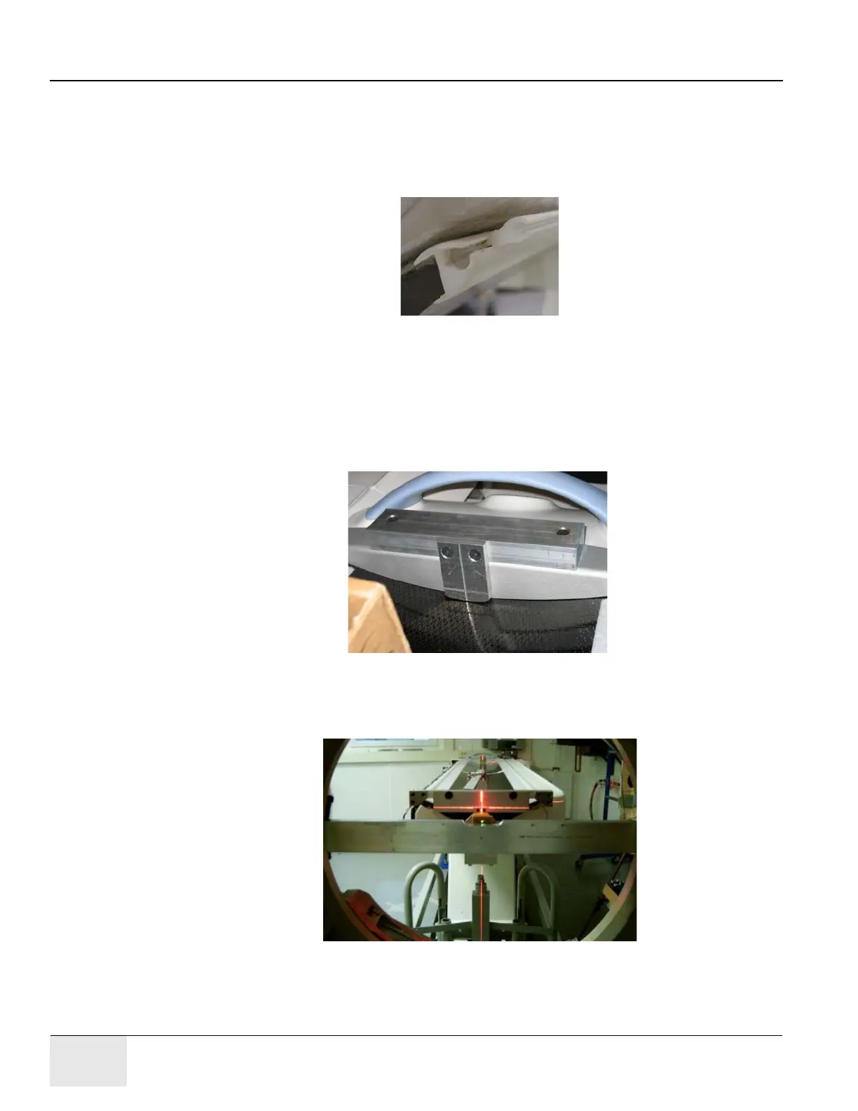
9.3.5 Install the Table Cradle Laser Alignment Plates
1.) Locate the aluminum accessory tray mounting plate with the three holes on the rear of the
cradle. Fit the rear alignment target into the two mounting holes as shown in Figure 1-33. Use
the adjustment screw to adjust the fit as needed. See Figure 1-33. The fit should be snug,
without play, when you are finished.
Figure 1-33 Cradle Rear Laser Alignment Tool
2.) Check that the table base is centered over the table center line, and the base is on the 26.5 in.
line (± 0.25 in.) made on the floor.
Figure 1-34 Rear Laser Alignment Tool - Installed
Adjustment
Screw
Mounting
Plate
Adjustment
Screw

 Loading...


