GE COMPANY
DIRECTION 5472001-1EN, REVISION 6OPTIMA CT680 SERIES AND OPTIMA CT670 INSTALLATION MANUAL
Chapter 2 - Power, Ground & Interconnect Cables Page 113
2 – Install Power
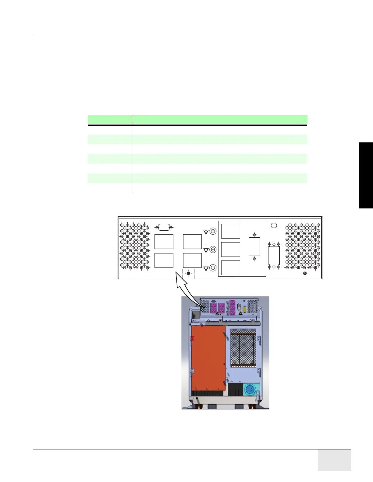
3.6 AC Box Connections
CAUTION The outlets are not for General Use. Operator Console outlet has a rating for 2.5A at 120VAC.
Accessories should not exceed above rating.
Note: Console power is single phase power. Outlet assigned is not critical.
1.) Connect the console power cable and ground cable to the console power panel.
2.) Connect console component power cords as listed in Table 2-10. (“J numbers” increment from
top to bottom, left to right)
Figure 2-16 AC Box Connections
Number Description
J9 Display Monitor Power Connection
J10 Scan Monitor Power Connection
J11 Peripheral Media Tower Power Connection
J12 In-Room Monitor Connection
J13 Injector Power Connection
J14 RPM Power Connection
J56 GSCB Power Connection
Table 2-10 AC Box Outlet Assignments
CB3
J13
J14
J55
JI-J6 & J9-J12 controlled by CB1;
J13, J14, J55 controlled by CB3.
J57
120V AC 2.5A 50/60HZ
J56
J10
J11
J12
J9
120V AC 10A 50/60HZ
12V DC
120V AC 10A 50/60HZ
120V AC 10A 50/60HZ
120V AC 10A 50/60HZ
120V AC 2.5A 50/60HZ
120V AC 2.5A 50/60HZ

 Loading...


