GE COMPANY
DIRECTION 5472001-1EN, REVISION 6OPTIMA CT680 SERIES AND OPTIMA CT670 INSTALLATION MANUAL
Chapter 1 - Position Subsystems Page 73
1 – Pos. Subsystems
Note: If alternate location(s) are used to anchor the table or gantry, you must move the respective
leveler(s) and pad(s) to the new alternate location(s) and re-drill.
11.4 Drilling Procedure (For Lite Table)
When the room-layout template is used, the anchor bolts have been installed. If it is, perform the
following. If it is NOT, perform all procedures of this section.
- Table Leveling (This section)
- Tighten the anchor nuts with the insulating plate and washer.
TORQUE: Approx. 5 N-m
NOTICE Do not tighten the anchor nuts to the specified torque (50 N-m). To over-tighten nuts will
damage the frame of the Gantry and also bring an out-of-level Gantry.
- Verify that the Table to Gantry Alignment should be correct.
This anchoring procedure is one for the anchor kit shipped with the system.
NOTICE The minimum Tensile load strength of the anchor must be 13000 N.
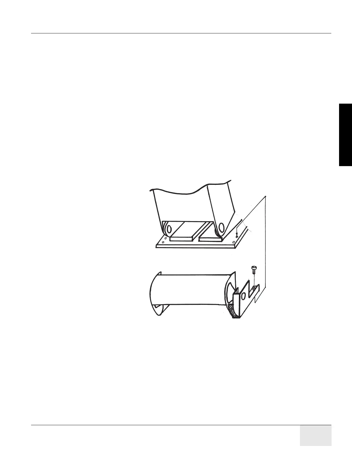
1.) Verify that the table flapper is removed to make space for anchoring. If it is not, remove the
table flapper by removing the four flapper Assy mounting bolts.
Figure 1-52 Table Flapper Removal
2.) Prepare and tape ½” concrete drill bit.
3.) Make holes at the anchor position as shown in Figure 1-37, using electric drill with the bit
prepared in the previous step, so that the lower edge of the tape just touch the floor surface.
NOTICE During drilling, always keep the drill bit perpendicular to the floor. With one person drilling
the hole, a second person can visually insure perpendicularity throughout the drilling
operation. Clear the hole of debris several times while drilling to prevent the drill bit from
binding.
Table Flapper
Flapper Bolts

 Loading...


