GE COMPANY
DIRECTION 5472001-1EN, REVISION 6OPTIMA CT680 SERIES AND OPTIMA CT670 INSTALLATION MANUAL
Chapter 1 - Position Subsystems Page 61
1 – Pos. Subsystems
CAUTION Potential for Injury.
In the ship position, the table tips easily!
DO NOT lean on the table! The shipping bracket should still be in place!
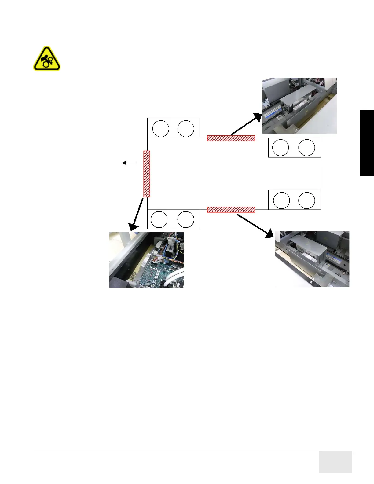
9.) Place the bubble level on the table base. Refer to Figure 1-37.
Figure 1-37 Level Location on the Table Base
10.) Raise or lower the table as needed using the front and rear levelers and level the table base
in the Z-direction (2 positions) and the Y-direction (1 position).
This process is complete when:
- The cradle is still centered on the front, mid, and rear marks.
- The cradle is leveled in the Z-direction at 2 positions shown in Figure 1-37.
- The bubble is leveled in the Y direction.
- The laser is still centered on the wall center line.
- The table is still on the 26.5" line and the levelers are not resting on the flooring.
- The laser is the same as in Step 7.
Note: The leveling process may take several iterations of Step 1 through Step 10. Patience and accuracy
is required to properly complete this process.
11.) When completed, turn off the laser tool.
Note: Do not remove the table dollies.
To Gantry
Z-direction
Level Location 2
Z-direction
Level Location 1
Y-direction
Level Location

 Loading...


