EasyManuals Logo
Home>GE>Switch>T1000

GE T1000 User Manual

GE T1000
302 pages
To Next Page IconTo Next Page
To Previous Page IconTo Previous Page
Page #269 background imageLoading...
Page #269 background image
Chapter 9 Installation
GE Reason Switches
REASON SWITCHES-TM-EN-3
269
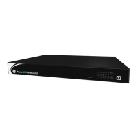
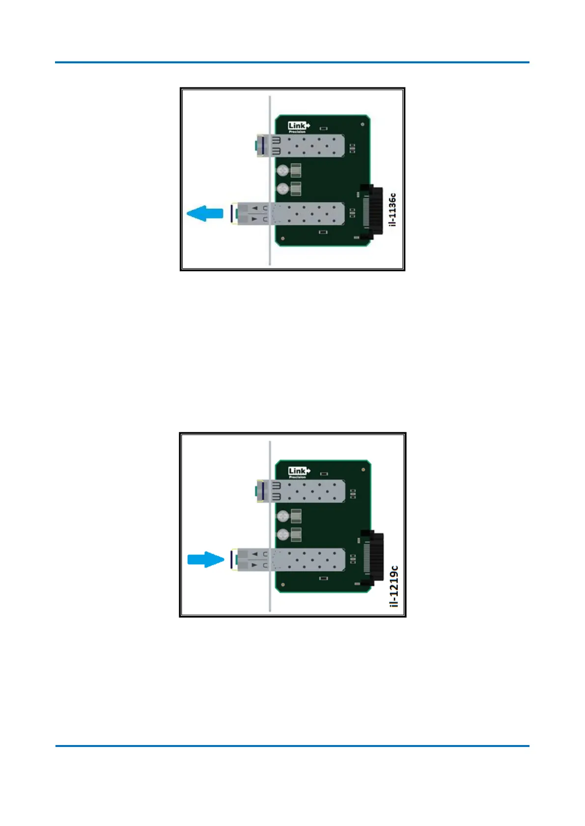
Figure 94: Removal direction of the SFP transceiver
Special attention should be paid when inserting the SFP transceiver. Figure below
illustrates the adequate orientation to SFP modules installed both in upper and lower
slots. When installing the SFP transceivers, these shall be inserted with the safety
catch locked in position.
Be sure that the SFP transceivers are completely inserted and that they are locked in
position at the end of its insertion.
Figure 95: Insertion module of the SFP transceiver

Table of Contents

Questions and Answers:

Question and Answer IconNeed help?

Do you have a question about the GE T1000 and is the answer not in the manual?

GE T1000 Specifications

General IconGeneral
BrandGE
ModelT1000
CategorySwitch
LanguageEnglish

Related product manuals