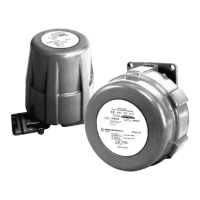
The figure below presents an example of these definitions. The number shown is the
bridge identifier, and also the path costs to the entire physical topology is shown. On
the example, all bridges priority and ports priority will be considered the same. Thus,
the logical topology will be defined based only on path costs and bridge identifier.
Furthermore, it is considered that all switches send and receive BPDU packets to
map topology and disable active loops
Figure 17: Example of a loop-topology showing bridge
In the example, the lowest bridge identifier is the Bridge 001. Thus, this switch will be
the root bridge.
The path that will be used to send data over the network will be defined based on the
path cost from the root bridge to the last node. If traffic from IED A to IED B goes
through bridges 001 and 500, the total cost will be 104. However, if traffic from IED A
to IED B goes through bridges 001, 050 and 100, the total cost will be 290. Thus, the
first path will be used.
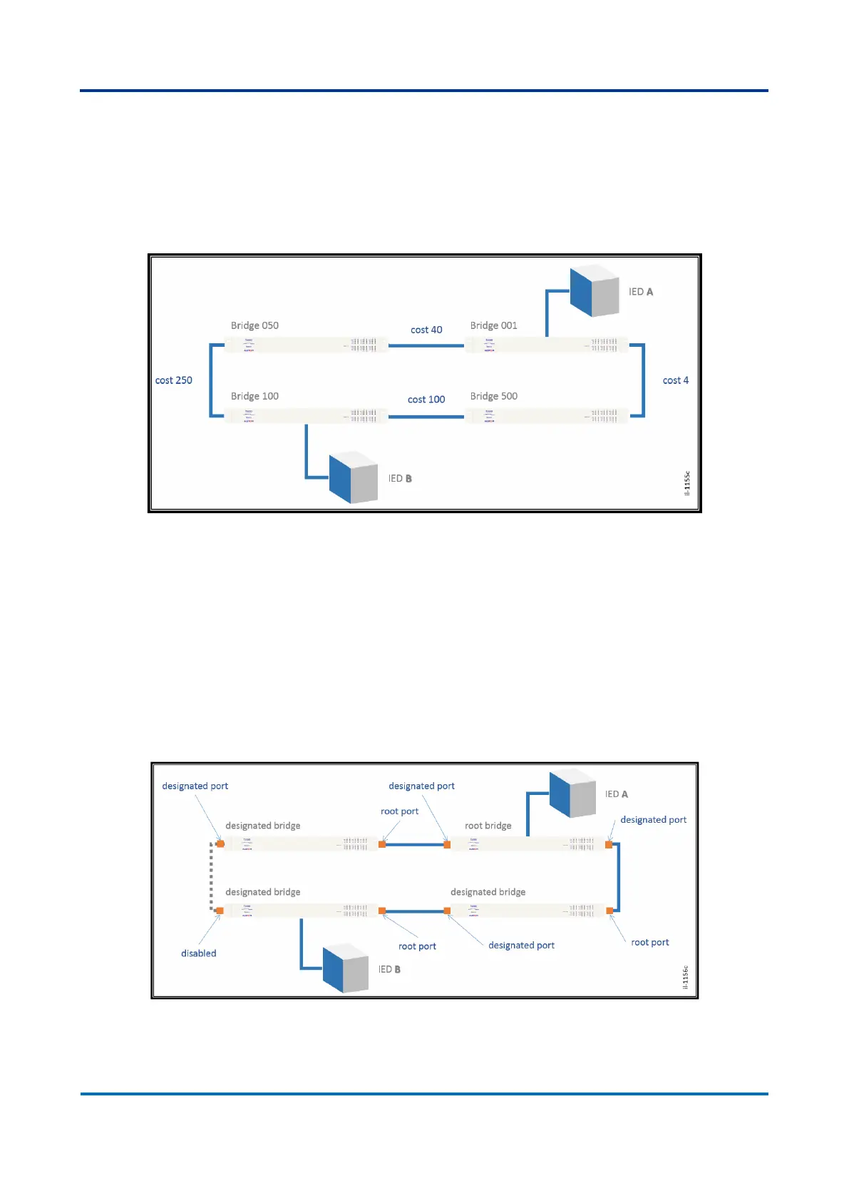
After the election, the active logical topology will be as follows.
Figure 18: Logical topology after the Spanning Tree protocol was executed
The previous figure also shows how ports are defined as root and designated port. In
case the port leads to a loop and it is the end of the tree branch, the port will be
 Loading...