16 ADL500 • Quick installation guide - Specifications and connection
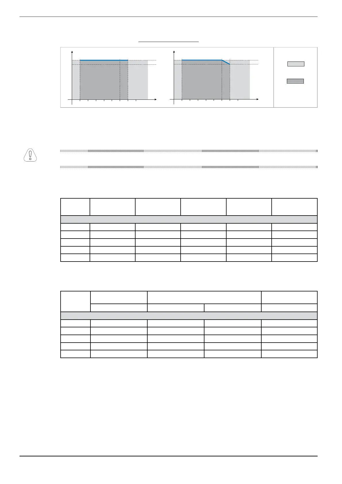
4.6.3 K: Ambient temperature reduction factor
Figure 4.6.3
1.00
Tamb (°C)
K
T
-10 40 500
0.90
1.00
Tamb (°C)
K
T
-10 40 500
ADL550
ADL510/ADL530
Function not allowed
Range of ambient
temperatures allowed
4.7
Voltage level of the inverter for safe operations
The minimum time between the moment in which an ADL500 inverter is disabled from the mains and that in which an
operator can operate on internal parts of the inverter, without the danger of electric shock, is 5 minutes.
inverter condition).
4.8
No-load consumption (Energy rating)
Size No. of pre-loads allowed Power-on
time
[secs]
Stand-by consumption
"Fan Off"
[W]
Fan consumption
[W]
Stand-by consumption
"Fan On"
[W]
ADL5...-...-4, 3ph
1040 1 each 20 sec. 5 abt. 20 8 28
1055 1 each 20 sec. 5 abt. 20 10 30
1075 1 each 20 sec. 5 abt. 20 10 30
2110 1 each 20 sec. 5 abt. 20 10 30
2150 1 each 20 sec. 5 abt. 20 16 36
4.9 Cooling
Size Pv
(Heat dissipation)
Fan capacity Minimum cabinet opening for
cooling
@U
ln=230...460Vac (*) Heat sink (m
3
/h) Internal (m
3
/h) (cm
2
)
ADL5...-...-4, 3ph
1040 150 2 x 35 - 72
1055 250 2 x 58 - 144
1075 350 2 x 58 - 144
2110 400 2 x 58 - 144
2150 600 2 x 58 - 328
(*) values that refer to operation at default switching frequency.
Attention
 Loading...


