40 ADL500 • Quick installation guide - Specifications and connection
Ip Assignment
IP Address setIP
Netmask set
- The PC IP netmask set to the same value as the IP Netmask set, parameter, PAR 9558;
- The PC IP addresss.
7.5 CAN interface
Note! For terminal location see section "7.1 Location and identification of terminals and LEDs" on page 26.
COMMUNICATION PROFILE for Industrial Systems; CiA Draft Standard 301 Version 4.2 Date 13 February 2002 by
CAN in Automation e. V.).
The ADL500 integrates the interface for connection to CAN networks and
(DS417 in preparation).
developed as a Minimum Capability Device. Data are exchanged cyclically; the master reads the data made available
by the slaves and writes the reference data to the slaves.
The interface is provided with functional isolation (> 1 kV).
Connection is via the CAN connector and no power supply is required.
Terminal Name Function Cable cross-section
L CAN_L CAN_L bus line (low dominant)
0.2 ... 2.5 mm
2
AWG 26 ... 12
SH CAN_SHLD CAN shielding
H CAN_H CAN_H bus line (high dominant)
LED Meaning
CAN (green)
Off Stop
Flashing Pre-operational
On Operational
must be laid separately from the power cables, at a distance of at least 20 cm. Cable shielding must be grounded at
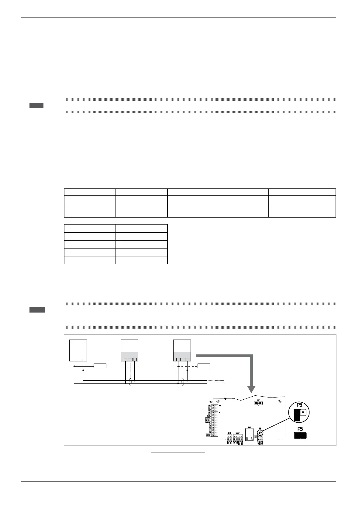
Note! As regards terminations: the first and last termination on the network must have a 120 ohm resistor between pins L and H or jumper P5 on the regula-
tion board can be turned (ON) (the top cover must be removed, see section "A.1.1 - Installation" on page 87 or set parameter 4008 Can Terminator = 1
(CAN1) on 6.1 CONTROL COMM menu.
CAN-H
MASTER
CANopen
120 ohm
L
ADL500
SH H
CAN
120 ohm
CAN-L
L
ADL500
SH H
CAN
Regulation card
OFF
(Default)
ON
Figure 7.5.1: CANbus connection
 Loading...


