ADL500 • Quick installation guide - Specifications and connection 27
7.2 Power section
Note! For the position of the terminals see section "7.1 Location and identification of terminals and LEDs" on page 26.
7.2.1 Power terminals and connection
Terminal Description IN/OUT ADL510/530/550 ADL510/530/550-EMS
L1 Three-phase main supply, phase L1 OUT
Yes Yes
L2 Three-phase main supply, phase L2 OUT
Yes Yes
L3 Three-phase main supply, phase L3 OUT
Yes Yes
BR1 Brake resistor IN
Yes Yes
BR2 Brake resistor OUT
Yes Yes
C1 DC choke (tie to C if not used) OUT
Yes Yes
C DC choke IN
Yes Yes
D DC Link (-) OUT
Yes Yes
U Motor connection, phase U OUT
Yes Yes
V Motor connection, phase V OUT
Yes Yes
W Motor connection, phase W OUT
Yes Yes
EM Battery main supply (+) IN -
(1)
Yes
(2)
(1) Do not use.
(2) Connect only emergency battery pack (+)
7.2.2 Cable cross-sections
Sizes
Terminals: L1 - L2 - L3 - BR1 - BR2 - C1 - C - D - U - V - W - EM
Maximum cable cross-section
(flexible conductor)
Recommended
stripping
Recommended
terminal
Tightening
torque (min)
(mm
2
) AWG (mm) (mm) (Nm)
1040 4 10 8 None / pin 0.5 ... 0.6
1055 4 10 8 None / pin 0.5 ... 0.6
1075 4 10 8 None / pin 0.5 ... 0.6
2110 16 6 10 None / pin 1.2 ... 1.5
2150 16 6 10 None / pin 1.2 ... 1.5
Sizes
Terminals:
on structural work
Cable cross-section
Lock screw diameter
Recommended
terminal
Tightening
torque (min)
(mm
2
) AWG (mm) (mm) (Nm)
1040 ... 2150
Same as the maximum cross-section used for the
power terminal strip
M5 Eyelet - Fork 6
Note! The minimum cross-section for both ground connections must comply with EN61800-5-1 prescriptions. Always ground both points on structural steel.
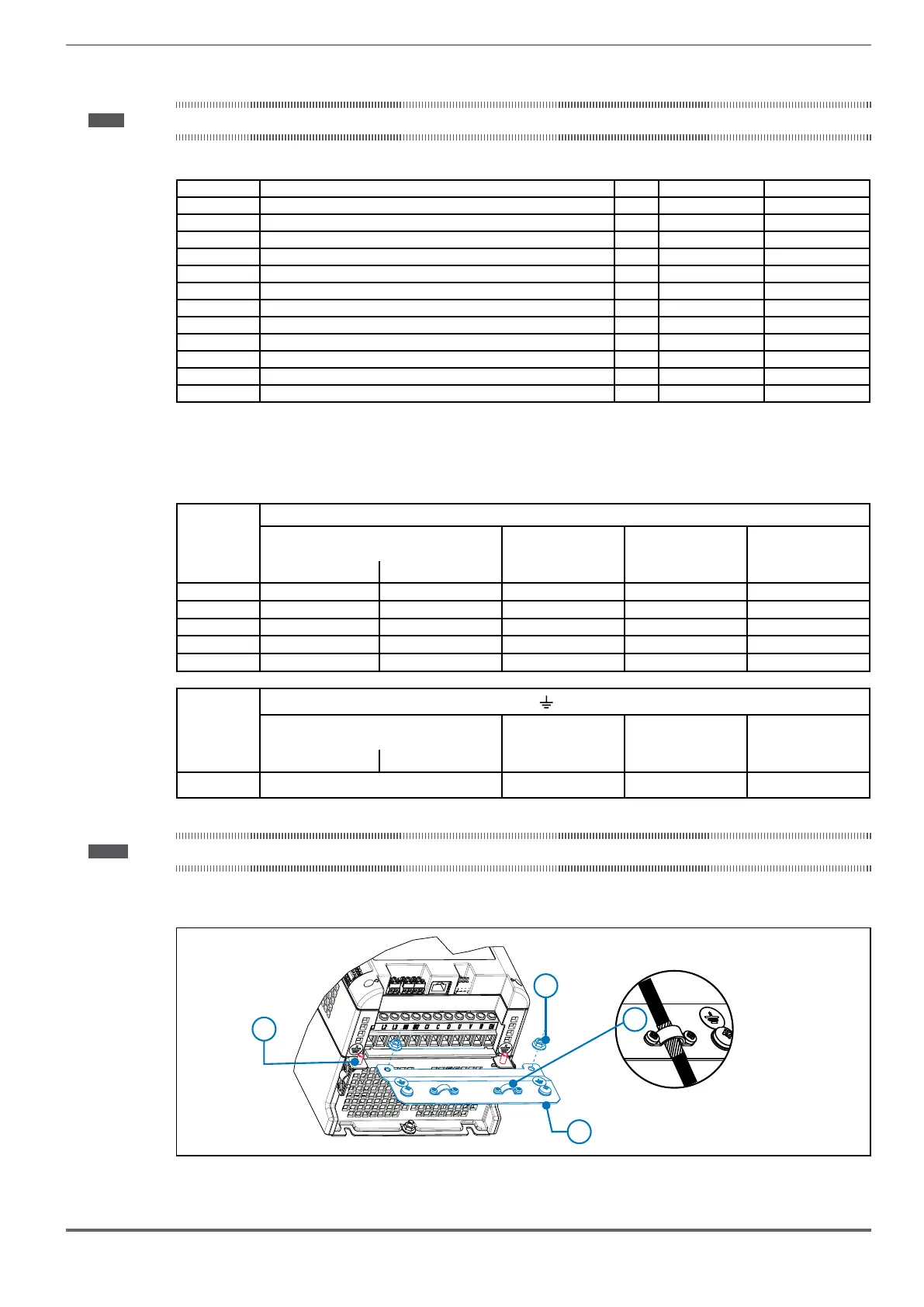
7.2.3 Connection of shielding (recommended)
C
D
A
B
Optional KIT-PWR SHIELD ASSY:
- Cod. S72684S12 (size 1)
- Cod. S72684S13 (size 2)
For compliance with EN 12016: put the optional metal support KIT-PWR SHIELD ASSY (A) on bolts (B) and tighten the
two nuts fully (C).
Fasten the power cable shield to the omega sections (D).
 Loading...


