ADL500 • Quick installation guide - Specifications and connection 93
A.4 - Brake monitoring system
A.4.1 Introduction
The brake monitoring function in the ADL500 series of products enables implementation of the automatic brake moni-
toring function as required by EN 81-20:2020 section 5.6.7.3.
Two functional elements are required to implement the brake monitoring function:
1. Management of the Brake fault alarm;
2. Resetting of the Brake fault alarm.
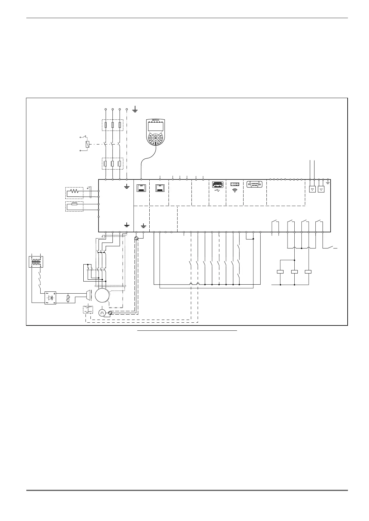
The basic wiring diagram for implementing this function is shown in Figure 5.1.
1
2
3
4
5
6
M
3
~
DC CHOKE
L2
(ADL550: 4 to 22kW)
ADL550
U1
V1 W1
U2
V2
W2
DOOR
CAN
DI8
DI7
DI6
DI5
DI4
DI3
DI2
DI1
ENHW
DICM
0VOUT
24VOUT
L1 L2 L3
KEYPAD
ETH-PC
T1 T2 T3
1 2 3 4 5 6 7 8 9 10 11 12
PE
PE
50
51
SH
H
L
D
C
BR1
BREAKING
RESISTOR
BR2
BRAKE
CONTACTOR
OK
DRIVE
52
53
54
55
CONTACTOR
RUN
56
57
L1
A1
A2
A1
A2
A1
A2
K2M
K3M BR
BRAKE
K2M
K3M
BR
TRAFO
3 Phase Mains
FBR
5
6
3
4
1
2
K2M
5
6
3
4
1
2
K3M
Emergency
Failure
(optional)
EN+
EN-
XE
XER
PE
OK1
OK2
C1
OPTIONAL
AC CHOKE
L1
OPTIONAL
F1
SFTY-STO
+24V (EXT)
+24V
0
EXP-DCP
(optional)
USB 2.0
DI4X
1
DI3X
2
DI2X
3
DI1X
4
DICM
5
EXP-4DI+2RO
(optional)
RO_5O
1
RO_5C
2
RO_6O
3
RO_6C
4
-
-
+
+
1 2 3 4
MOT-
MOT+
AI_1P
AI_1N
Motor PTC
Brake fbk
MltSpd S1
Brake 2 fbk
Emergency mode
MltSpd S0
StartFwdCmd
StartRevCmd
K2M
K3M
Safety
chain
OPTIONAL
OPTIONAL
S1
US1
S2
Figure 5.1: ADL550 connection diagram for brake monitoring
This shows that :
A) The ADL500 controls brake activation/deactivation via relay BR
B) Both brake feedback signals are sent to the ADL500 inputs
C) The ADL500 signals any malfunctions (including brake malfunctions) to the system control unit via internal relay
DRIVE OK.
D) The system control unit blocks the system brake in safety by deactivating contactors K2M and K3M.
According to an alternative arrangement, the ADL500 closes/opens contactors K2M and K3M but the power supply to
the coils and to the ADL500 commands comes from the external, i.e. a control unit.
The purpose of the brake fault alarm is to check whether the states of the two feedback signals from the brake are
consistent and, in case of doubt, to include a function whereby the ADL500 drive stops the system. The procedure for
including the alarm is described below.
A.4
• Activation of the brake fault alarm function.
The installer must have previously located the necessary digital inputs of the ADL500 drive and connected the cor-
responding wires to the feedback signals on these inputs. Note that depending on the type of wiring arrangement, the
brake feedback signals are normally asserted (brake closed – digital input to 1) or normally not asserted (brake closed
– digital input to 0).
 Loading...


