50 ADL500 • Quick installation guide - Specifications and connection
7.10 Braking
There are various possible types of braking:
- Internal Braking Unit
- Injection of direct current from the Inverter into the motor (D.C. braking)
- A braking unit can be used for speed reduction (e.g.: from 1000 to 800 rpm), whereas D.C. braking can only be
usedfor braking to standstill.
- The energy in the drive is converted into heat in both cases. This conversion takes place in a braking resistor
encased in the braking unit. With D.C. braking, the energy is converted into heat in the motor itself, resulting in a
further rise in motor temperature.
7.10.1 Braking unit (internal)
Frequency-regulated asynchronous motors during hyper-synchronous or regenerative functioning behave as genera-
This leads to an increase in the intermediate circuit voltage.
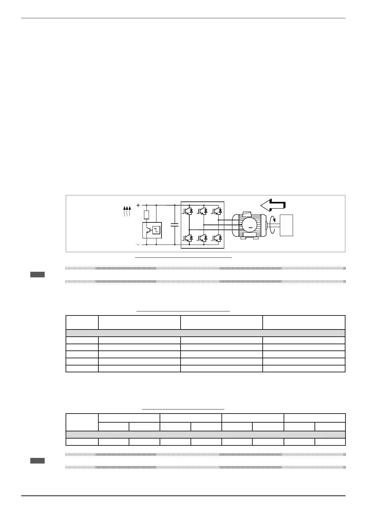
Braking units (BU) are therefore used in order to prevent the DC voltage rising to an impermissible value. When used,
these activate a braking resistor that is connected in parallel to the capacitors of the intermediate circuit. The feedback
energy is converted to heat via the braking resistor (R), thus providing very short deceleration times and restricted
four-quadrant operation.
55kW) comprise an internal braking unit.
E
3
M
_
R
BR
BU
U
ZK
Figure 7.10.1: Operation with braking unit (circuit diagram)
Note! When the internal braking unit is present the protection must consist of fast-acting fuses! Follow the relative assembly instructions.
A twisted cable must be used for the connection of the braking resistor (terminals BR and C or BR1 and BR2). If the
resistor includes a thermal protection device (Klixon), this must be connected to the "External fault" input of the drive.
Tabella 7.10.1: Technical data of the internal braking unit
Size IrmS
(A)
Ipk
(A)
Rbr
(Ω)
ADL5...-...-4, 3ph
1040 8.3 11.8 68
1055 8.3 11.8 68
1075 11.5 16.3 49
2110 20.2 28.5 28
2150 20.2 28.5 28
I
I Peak current that can be delivered for max 60 seconds
R Minimum braking resistance value
Tabella 7.10.2: Braking unit intervention threshold
Size
Vbr @ 480 V Vbr @460 V Vbr @ 400 V Vbr @ 230V
ON
OFF
ON OFF ON OFF ON OFF
ADL5...-...-4, 3ph
1040 ... 2150 800 Vdc
790 Vdc
768 Vdc 758 Vdc 670 Vdc 660 Vdc 394 Vdc 384 Vdc
Note! For the combination of recommended braking resistors refer to chapter "5.4 External braking resistors" on page 19.
 Loading...


