ADV200 • Functions description and parameters list 117
22.8–FUNCTIONS/SPEEDCAPTURE
This function allows the drive to capture a motor running due to inertia or driven by the load. The function is
also enabled in case of an automatic restart after an alarm condition.
Main elds of application:
- Capturing a motor set in motion by the load (for example pump motors driven by the uid)
- Capturing a motor connected directly to the power mains
- Capturing a motor running due to temporary disabling of the drive
- Capturing a motor that is running in the case of an automatic restart after an alarm
Note ! If the drive is enabled with the motor running and this function disabled, the drive could be blocked due to the intervention of the
Overcurrent or Undercurrent protections
Menu PAR Description UM Type FB BIT Def Min Max Acc Mod
22.8.1 3350Speedcapture ENUM Disable 0 1 ERW FV_
This parameter is used to enable the function to capture a motor that is running.
0 Disable
1 Alarm restart
2 Enable&restart
If set to 0 the capture running motor function is disabled. The output frequency starts from 0 and passes to the set
reference value using the ramp.
If set to 1 the capture running motor function is executed at restart each time an alarm is automatically reset.
If set to 2 the capture running motor function is executed each time the drive is enabled and each time an alarm is
automatically reset.
This function is available with Regulationmode=FluxvectorCL (asynchronous and synchronous motors) or V/f
control(asynchronous motors).
This function is not available with Regulationmode=FluxvectorOL.
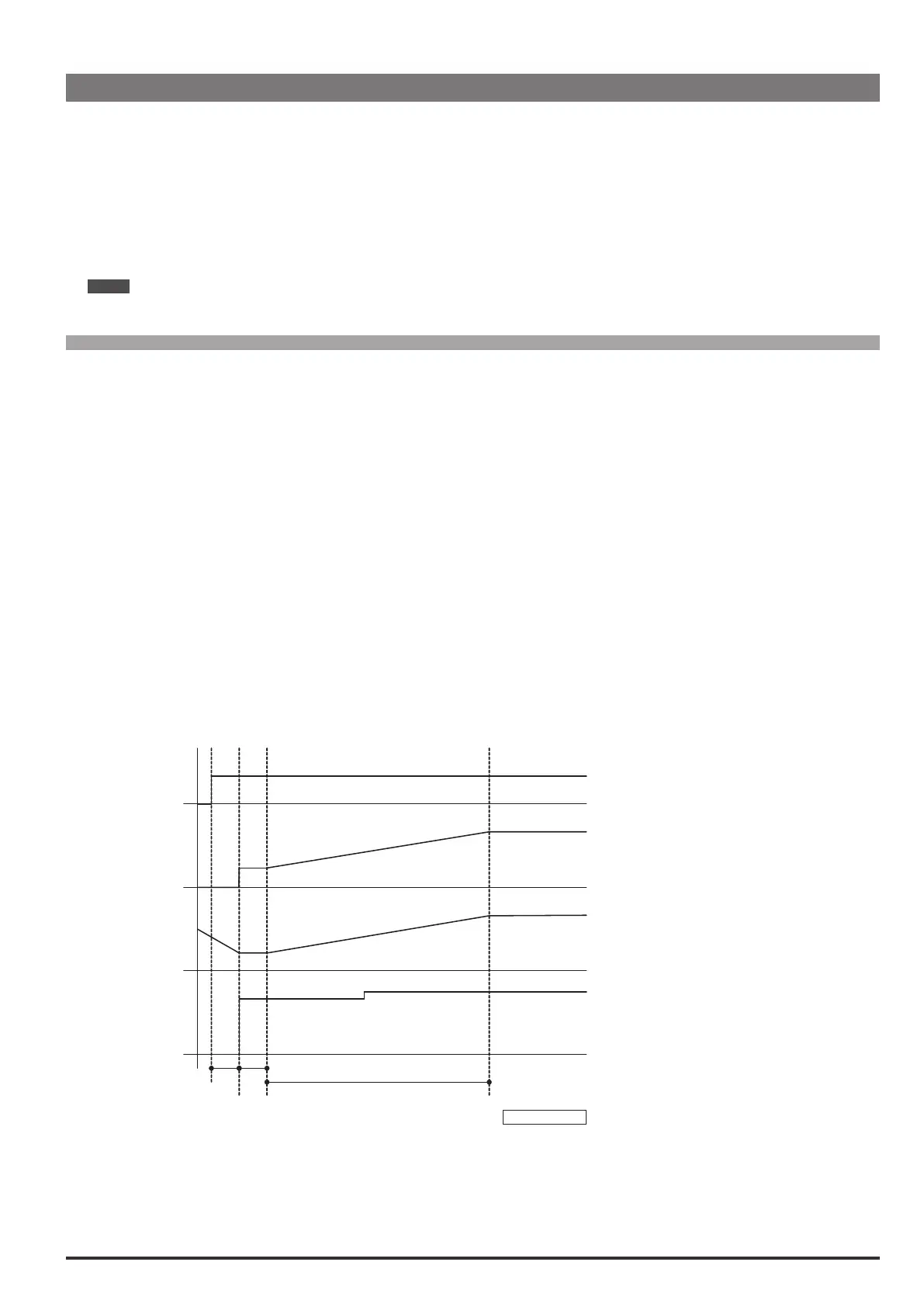
With Regulationmode=FluxvectorCL the capture procedure consists of forcing the output frequency to the
value measured by the encoder, and then bringing the motor speed to the reference value using the ramp
SpeedCapture_00.vsd
OutFreq
MotorSpd
OutCurr
Par 3366
Waiting for demagnetiz
Acceleration
Magnetiz
Flux vector CL
With Regulationmode=V/fcontrol the capture procedure consists of altering the inverter output frequency
until the actual motor speed is detected, then increasing the motor speed to the reference value using the
ramp. The procedure can take several seconds, depending on the type of load and parameter settings. If
this function is enabled on a motor at speed = 0 and drive speed reference = 0, the motor might start running
until the moment the drive detects the actual motor speed, after which the motor speed passes to the speed
reference setting, i.e. 0. The initial value of the output frequency depends on the condition that generated the
 Loading...


