ADV200 • Functions description and parameters list 5
A–Programming
A.1Menudisplaymodes
The programming menu can be displayed in two modes, which can be selected using the Accessmode pa-
rameter (04 - DRIVE CONFIG menu):
• Easy(default) only the main parameters are displayed.
• Expert all the parameters are displayed
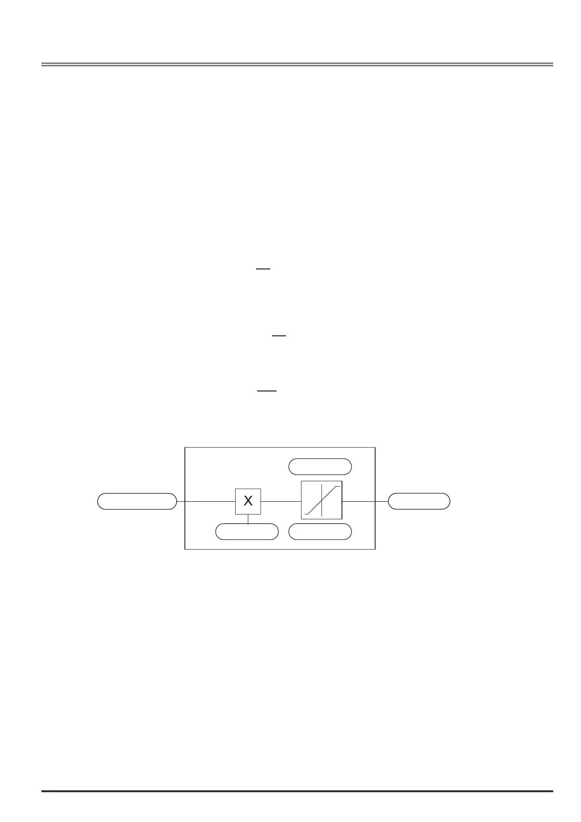
A.2Programmingof“functionblock”analoganddigitalinputsignals
The signals, variables and parameters of each single “function block” of the drive are interconnected in order to
achieve the congurations and controls inside the control system.
These can be managed and modied using the keypad, PC congurator or eldbus programming.
The programming mode is based on the following logic:
Src (source; i.e.: Rampref1src, PAR: 610)
This term denesthesourceofthefunctionblockinput, i.e. the signal to be processed in the
function block.
The different congurations are dened in the relative selection lists
.
cfg (conguration; i.e.: Mpotinitcfg, PAR: 880)
This term refers to the parameter setting and its effect on the function block.
For example: Ramp times, internal reference adjustment, etc...
mon (display; i.e.: Rampref1mon, PAR: 620)
This term refers to the variable output from the function block, which is the result of the
calculations performed on the actual block
.
Input selected
Parameter
Parameter
Parameter
Variable
Cfg
src Monitor
Function block
A.3Variableinterconnectionsmode
Thesource(src) allows the desired control signal to be assigned to the function block input.
This operation is performed by using specic selection lists.
Possible control signal sources:
1–Physicalterminal
The analog and digital signals come from the terminal strip of the regulation card and/or from those of the
expansion cards.
2–Driveinternalvariables
Internal drive control system variables, from “function block” calculations, sent via keypad, PC congurator or
eldbus.
 Loading...


