ADV200 • Functions description and parameters list 9
Note ! The drive is factory-set to control Asynchronous motors. To switch to Synchronous mode, send the Loadsynchcontrolcom-
mand (In menu 4 DRIVE CONFIG, first set PAR 554 Accessmode = Expert, then again in menu 4 - DRIVE CONFIG, run parameter
6100 Loadsynchcontrol). The drive is re-started (in this mode, reference should be made to the “ADV 200 – Field-oriented vec-
tor inverter for synchronous motors – Description of functions and list of parameters” guide on the CD supplied with the inverter
or downloadable from the www.gefran.com website).
To return to Asynchronous motor control mode, send the Loadasynchcontrolcommand (PAR 6100). The drive is re-started to
operate in the new mode.
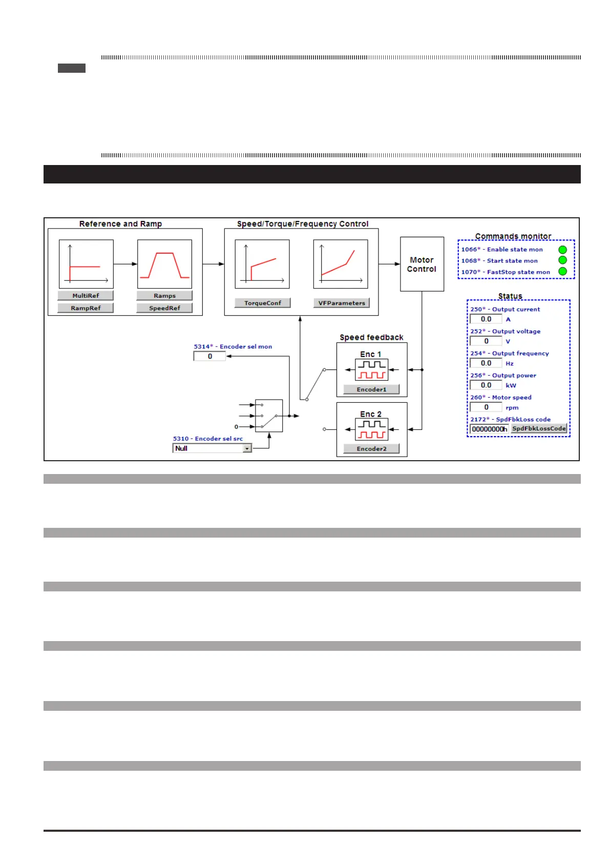
1–MONITOR
The monitor menu displays the measured values of the sizes and of the drive operating parameters.
Menu PAR Description UM Type FB BIT Def Min Max Acc Mod
1.1 250 Outputcurrent A FLOAT 16/32 0.0 0.0 0.0 R FVS
The drive output current is displayed.
Menu PAR Description UM Type FB BIT Def Min Max Acc Mod
1.2 252 Outputvoltage V FLOAT 16/32 0.0 0.0 0.0 R FVS
The drive line voltage output is displayed.
Menu PAR Description UM Type FB BIT Def Min Max Acc Mod
1.3 254 Outputfrequency Hz FLOAT 16/32 0 0 0 R FVS
The drive output frequency is displayed.
Menu PAR Description UM Type FB BIT Def Min Max Acc Mod
1.4 256 Outputpower kW FLOAT 16/32 0.0 0.0 0.0 R FVS
Displays the drive output power.
Menu PAR Description UM Type FB BIT Def Min Max Acc Mod
1.5 628 Rampsetpoint FF INT16 16/32 0 0 0 R FVS
The ramp reference is displayed. This is the speed value the drive must reach at the end of the ramp.
Menu PAR Description UM Type FB BIT Def Min Max Acc Mod
1.6 664 Speedsetpoint FF INT16 16/32 0 0 0 R FVS
The speed reference is displayed. This is the value measured at the output of the speed reference circuit.
 Loading...


