819XX_MAN_GRM-H_11-2022_ENG_pag. 47
5.2.4.2. Function for pin13 input/output
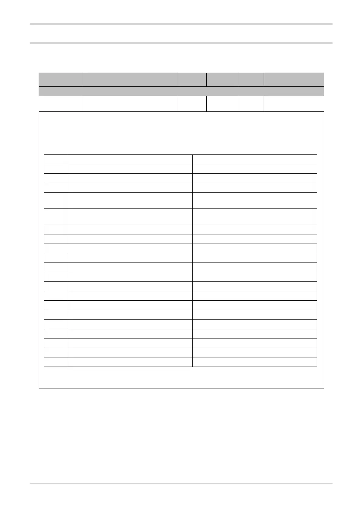
Acronym App / GF_eXpress menu Attribute Retentive U.M. Default
Description
io.13
Inputs/Outputs R/W
■
1
Function for input or reference for output relative to pin13 (for GRM-Hxx-AN-xx-xx-xxx models only).
In the case of potentiometer input, digital input 1 operations have no effect and the terminal on the
connector is used as the potentiometer power supply output.
Options:
Value Function Notes
0 I/O disabled
1 In - HB calibration Rising edge
2 In – Feedback Calibration Rising edge
3 In – Software OFF In=1: Software Off ,
In=0: Software On
4 IN - HB and PF alarm memory reset In=1: Alarms reset,
In=0: Normal alarm status
5 In – Dryout restart Rising edge
6 In – Dryout end Rising edge
14 In – MAN/AUTO control In=1: MAN, In=0: Auto
15 In – SSR Main In=1: SSR ON, In=0: SSR OFF
16 In – PMW Control (Ou.P) See parameter PWM.t and PWM.f
32 Out – HB or PF alarms
33 Out – HB alarm
34 Out – PF alarms
35 Out - SSR overtemperature
36 Out – HB or PF alarms or Overtemperature
37 Out – HB alarm or SSR overtemperature
38 Out – PF alarms or SSR overtemperature
39 Out – Dryout status
40 Out – Communication error
47 Out – POT Power Forced to 47 if tyP=5 or 6
5.3. Inputs/Outputs

 Loading...


