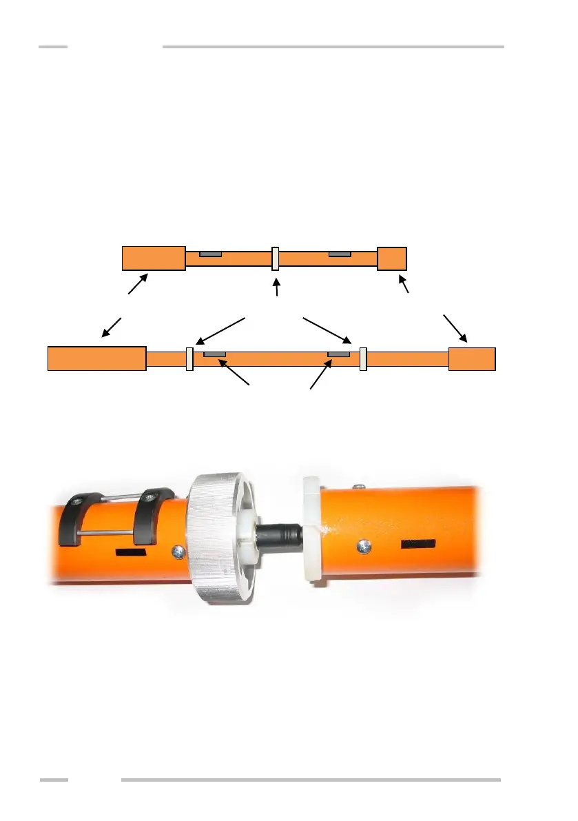
Probes CMD-2 and CMD-4
Put arms of the probe to each other having black strips in one line - the arm
with longer cover (transmitter) to the left and the arm with shorter cover (receiver)
to the right. In the case of CMD-4 the transmitter arm is labeled with simple black
strip and the receiver with black “T”. Then connect the connector and assemble the
arms by turning the bayonet rings. See pictures below.
If you wish to measure with maximum depth range (HIGH), turn the probe
to position with the black strip and “Hi” label on the upper side. If you wish to
measure with half depth range (LOW), turn the probe to position with the black
strip and “Lo” label on the upper side.
 Loading...