Introduction
The CMD conductivity meters serve for fast contactless measurement of
ground conductivity and in-phase (closely depending on magnetic susceptibility).
Measured data can be used for conductivity maps from one or several depth levels
and for conductivity sections. Thus it can be used for many tasks in the frame of
geological and civil engineering survey, agriculture, environmental monitoring,
groundwater protection, raw material prospecting, archaeology, metal objects and
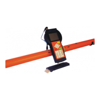
networks detection. Walking and vehicle applications of CMD instruments allow
performing measurements even in exacting conditions like dry or icy soil.
The comfortable and transparent way of CMD operation minimizes
requirements for the user keeping reliability and many highlights like:
(For details see Technical specifications.)
- two manual and two continuous measuring modes with GPS or length-mark
positioning
- minimum need of settings and calibration checking
- fast response
- high resistance against electromagnetic noise
- very low weight and power consumption
- good visibility of the graphic display under all conditions
- large memory capacity
- easy data transfer to PC using USB or USB Flash disk
- compatibility with common mapping and inversion SW (Surfer, Geosoft,
Interpex)
- integrated Bluetooth for wireless operating of the probe or GPS receiver
The used physical principle of measurement together with sophisticated
technical solution has been successfully applied for many years of production of
electromagnetic conductivity meters in GF Instruments. Now it allows offering
wide family of calibrated instruments with defined depth ranges and high
temperature stability.
The measurement is based on evaluation of induced secondary magnetic field from
ground. The transmitter generates pure sine wave of magnetic field with
vertical/horizontal dipole orientation. The receiver with the same dipole orientation
is placed on the arm with proper length with respect to the nominal depth range at
low induction number. The received secondary magnetic field consists of
imaginary part (out-of-phase) which is proportional to the ground conductivity and
calibrated in mS/m and of real part (in-phase) which is determined by magnetic
properties (significantly influenced by ferromagnetic objects) and shown in ppt of
the primary field.
 Loading...