Home
Haier
Air Conditioner
Super Match 3U24GS2ERA
Haier Super Match 3U24GS2ERA User Manual
5
of 1
of 1 rating
483 pages
Give review
Manual
Specs
To Next Page
To Next Page
To Previous Page
To Previous Page
Loading...
Intuoduction
Domestic
air
conditioner
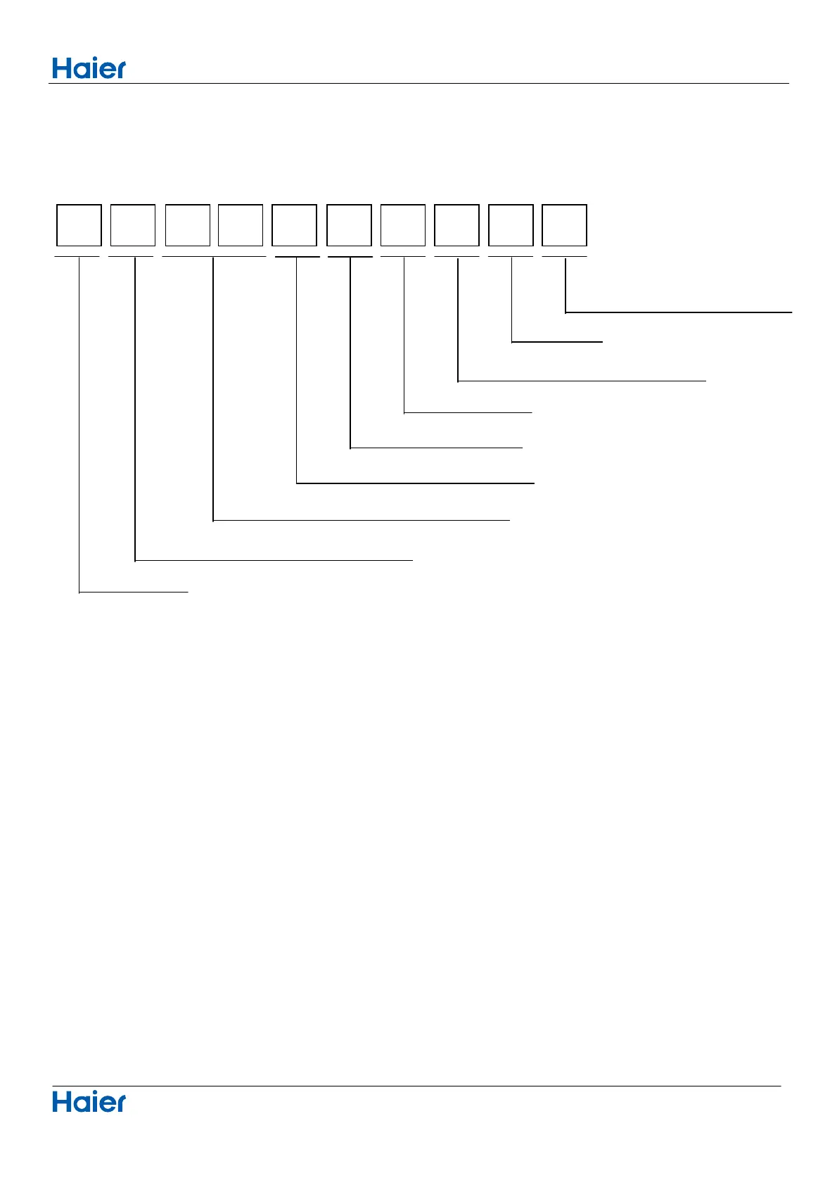
1 Introduction
1.1
Model
name
explanation
A
S
2
4
N
E
1
H
R
A
Indoor
unit
T
ype
of
indoor
unit:
S
(wall-mounted)
Nominal
cooling
capacity
(24000BTU/h)
V
ersion
number
Heat
pump
&
R410A
refrigerant
DC
inverter
Apply
toT1;
220~240V50HZ/1ph
Platform
of
indoor
units:
N
(N
plat
form)
70N
Platform
433
433
435
Table of Contents
Table of Contents
2
Part 1 General Information
3
Indoor / Outdoor Unit Models
4
Feature
5
General Stop Valve View
5
Part 2 Indoor Units
7
4-Way Cassette
8
Features
9
Speci Ication
10
Specification (4-Way Cassette)
10
Dimension
13
Piping Diagram
14
Wiring Diagram
15
Air Velocity and Temperature Distribution
17
Sound Pressure Level
21
Installation
24
Selection of Installation Place
24
In the Case of Ceiling Already Exists
25
In the Case of New Ceiling
25
Installation of Indoor Unit
25
Installation of Water Drainage Pipe
26
Refrigerant Piping
26
Cautions for the Drain Water Lifting Pipe
27
Limits of Panel Board Installation
27
When Wiring Is Not Complete
27
Wiring
28
Duct Indoor
29
Features
30
Specification (Duct Indoor)
32
Dimension (Duct Indoor)
39
Piping Diagram (Duct Indoor)
41
Wiring Diagram (Duct Indoor)
42
Air Flow and Static Pressure Curves
44
Air Flow and Static Pressure Chart
46
Air Velocity and Temperature Distribution
46
Sound Pressure Level (Duct Indoor)
48
Installation (Duct Indoor)
52
Maintenance
52
Parts and Functions (Duct Indoor)
52
Selecting the Mounting Position to Install the Indoor Units
53
After Selecting the Unit Installation Location
53
Installatoin Dimension
53
The Sketch Map of Long Duct
54
Thermal Insulation of Duct
54
Installation of Air Return Duct
54
Installation of Air Sending Duct
54
Installing the Suspension Screw
55
Wooden Sctructure
55
Steel Reinforcement Structure
55
Connection of Refrigerant Pipe
55
Insulation Treatment
56
Installation Requirements
56
Pipe and Insulation Material
56
Wiring Connection
57
Drain Confirmation
57
Precautions for Electrical Wiring
57
Hose
57
Parts and Functions Diagram
58
Applicable Ambient Temperature Range
58
Preparation of Indoor Unit
59
Preparation for Suspending the Unit
60
Installation of Indoor Unit (Duct Indoor)
60
Adjusting the the Levelness
60
Tap Selection on Blower Unit
60
Drain Piping
61
Connection of Suction, Exhaust Ducts
62
Installation Work for Air Outlet Ducts
62
Drainage Test
62
Selection of Size of Power Supply and Interconnecting Wires
63
Wiring Connection (Duct Indoor)
63
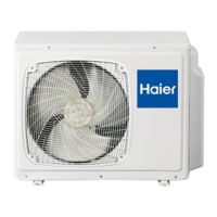
Part 3 Outdoor Unit
64
Outdoor Unit Specification
65
Dimension (Outdoor Unit)
69
Wiring Diagram (Outdoor Unit)
71
Wiring Connection (Outdoor Unit)
73
Piping Diagram (Outdoor Unit)
76
Refrigerant Diagram
76
Limitation Values on Pipe Instalaltion
79
Connection Cautions
82
Sound Level (Outdoor Unit)
83
Sound Pressure Level
83
Outdoor Performance Curves
86
Instalaltion
90
Maintenance (Outdoor Unit)
90
Precautions for Handling Units for Use with R410A
92
Before Installing (Relocating) the Unit or Performing Electric Work
93
Befor the Test Run
93
Items to be Checked
94
Necessary Tools and Materials
94
Flare Nut
95
Types of Copper Pipes
95
Flare Machining
95
Piping Materials/Radial Thickness
95
Air Tightness Test
96
Vacuuming
96
Charging Refrigerant
96
Characteristics of the Conventional and the New Refrigerants
96
Procedure for Selecting the Location (Outdoor Unit)
97
Installation Drawings of Indoor and Outdoor Units
98
Limitations on the Installation (Outdoor Unit)
99
Selecting a Location for Installation of the Indoor Units
99
Outdoor Unit Installation Guideline
99
Precautions on Installation (Outdoor Unit)
99
Refrigerant Piping Work (Outdoor Unit)
100
Drain Work (Outdoor Unit)
100
Purging Air and Checking Gas Leakage
101
Refilling the Refrigerant
102
Charging with Refrigerant
102
Precautions for Laying Refrigerant Piping
102
Selection of Copper and Heat Insulation Materials
102
Cutting and Flaring Work of Piping
103
On Drainage
103
Wiring Method of Outdoor Unit
104
Electric Wiring
104
Wiring Work
104
Pump down Operation
104
Wiring Method of Indoor Unit
105
Example Wiring Diagram
105
Test Running
106
Wiring Error Check
106
Seven-Segment Numeric Display
106
Communication LED
106
Dred Function
107
Open Cover Piece and Locate the Fixed DRM Cable
107
Part 4 Electric Control and Debugging
108
Indoor Unit PCB
109
Indoor Unit Dip Switch Setting and Function
111
Compulsory Defrosting Operation
113
Indoor Unit Function
113
Trial Operation
113
Water Pump Control
113
Anti-Cold Air Control
114
Control for Discontinuous Operation
114
Fan Motor Control in Defrosting
114
Swing Motor Control
114
Healthy Negative Ion Function
115
Sleep Function
115
Timer Operation
115
Anti-Freezed Protection
116
Auto-Restart Function
116
Room Card Function
116
Setting Method of Temperature Compensation Tcomp
116
Outdoor Unit PCB Photo, Dip Switch Setting and Function
117
Dip Switch Setting
121
4-Way Valve Control in Heating
122
Electric Heater Control
122
Electronic Expansion Valve (EEV) Control
122
Outdoor Unit Control
122
Compulsory Defrosting Control
123
Control of Defrosting in Heating
123
Defrosting Operation Flow Chart
124
Frequency Control When Td Is too High
125
Frequency Control When There Is CT over Current Protection
126
High Pressure Protection (Multi)
126
Low Pressure Protection (Multi)
126
Diagnostic Code
128
Indoor Unit Troubeshooting
129
Trouble Shooting
131
No Display on the Operation Panel
132
Sensor Failure
132
Communication Failure between Indoor and Outdoor
133
Indoor PCB EEPROM Data Is Wrong
133
Indoor Repeated Unit Number
133
Outdoor Unit Failure
133
AC Current over Current Protection or Current Transducer Damaged
134
High Pressure Failure
134
Outdoor Unit Alarms Sensor Failure
134
Low Pressure Switch Failure
135
Base Operation
136
Controller Function
136
Loading of the Battery
136
Remote Controller
136
Power/Quiet Operation
137
Sleep Operation
137
Timer On/Off On-Off Operation
138
Healthy Airflow Operation
138
Important Information Regarding the Refrigerant Used
138
Display of the Wire Controller
139
Buttons of the Wire Controller
140
On/Off Operation
141
Present Time Setting
142
Setting of Power Failure Compensation Function
142
Timing Setting
143
Cancel Timing
143
Query Indoor Malfunction History
144
How to Change the Function Switches?
144
Installation Manual for Wire Controller
145
Install the Controller Holder
145
Wiring Instruction
145
Wiring Connections of Wire Controller
145
Communication Wiring
146
Wired Controller
147
Key Instructions for the Wired Controller
148
Main Interface Display of the Wired Controller
149
To Set Air Speed
151
Explanation of the Icons of the Wired Controller
151
Default Air Speed Upon Initial Energization
151
Display and Adjustment of Air Speed
151
Time Setting of Timing Switch
152
Deletion of Timing Information
152
Timing Switch On/Off Conflict Prompt
152
Current Clock Setting
153
Service Setting
154
Password Setting
154
Fault Code Query
155
Restore the Initial Password
155
Air Direction Setting
156
Sleep Setting
157
Unit Number Setting
158
Mode Lock Setting
158
Additional Functions
160
Filter Screen Cleaning
160
Temperature Compensation
160
Detailed Information
162
State Setting
162
Screen Saver
163
The Handling of Centralization/Lock Mode
163
Installation of Wire Controller
165
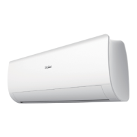
Wall Mounted Type
166
Af09Ab1Hra
166
Introduction
168
Model Name Explanation (Wall Mounted Type)
168
Caution in Repair (Wall Mounted Type)
169
Safety Cautions (Wall Mounted Type)
169
Cautions Regarding Products after Repair
170
Inspection after Repair (Wall Mounted Type)
172
Using Icons List
173
Features (Wall Mounted Type)
174
Specifications (Wall Mounted Type)
175
Sensors List
176
Piping Diagrams (Wall Mounted Type)
177
Printed Circuit Board Connector Wiring Diagram
178
Functions and Control
181
Cooling Operation Mode (Wall Mounted Type)
181
Main Functions and Control Specification of Indoor Unit (Wall Mounted)
181
Automatic Operation (Wall Mounted Type)
181
Dehumidifying Mode (Wall Mounted Type)
182
Heating Operation Mode (Wall Mounted Type)
182
Strength Operation (Wall Mounted Type)
183
Mute Operation
184
Air Refreshing
184
Timing
184
Dormant Operation
184
Low Load Protection Control
185
Urgent On/Off Input
185
High Load Protection Control
186
Abnormal Operation of Indoor System
186
Malfunction List Resume
186
Abnormality Confirmation Approaches
186
Single Indoor System Operation
187
Power Cut Compensation
187
Fixed Frequency Operation
187
Transmission Abnormality
187
The Operation Frequency of Outdoor Unit and Its Control
188
Test Program
188
Time Cutting Function
188
The Control System of Outdoor Unit
188
Value of Thermistor
189
System Configuration (Wall Mounted Type)
192
Parts and Functions (Wall Mounted Type)
193
Base Operation (Wall Mounted Type)
194
Emergency Operation and Test Operation (Wall Mounted Type)
194
Air Flow Direction Adjustment
195
Timer On/Off Operation
195
Power/Quiet Operation (Wall Mounted Type)
196
Sleep Operation (Wall Mounted Type)
196
Indoor Unit Installaion (Wall Mounted Type)
197
Accessory Parts
197
Selection of Pipe
197
Removal of Front Grille
198
Drawing of Pipe
198
Fixing the Indoor Unit Body
198
Removing the Wiring Cover
198
Check for Installation and Test Run (Wall Mounted Type)
199
On Drainage (Wall Mounted Type)
199
Cutting and Flaring Work of Piping (Wall Mounted Type)
199
Power Source Installation
199
Maintenance
200
For Smart Use of the Air Conditioner
200
Air Filter Cleaning
200
Clean the Indoor (Outdoor) Unit
200
Cautions
201
Troubleshooting (Wall Mounted Type)
202
Dimensional Drawings (Wall Mounted Type)
203
Center of Gravity (Wall Mounted Type)
203
Problem Symptoms and Measures (Wall Mounted Type)
204
Service Diagnosis (Wall Mounted Type)
204
Parameter of Primary Electronic Appliance
204
Error Codes and Description
205
Thermistor or Related Abnormality
206
Thermistor Resistance Check Method
206
EEPROM Abnormal
207
Indoor AC Fan Motor Malfunction
208
Outdoor DC Fan Motor Fault
209
IPM Protection
211
Over-Current of the Compressor
212
The Communication Fault between IPM and Outdoor PCB
213
Power Supply over or under Voltage Fault
214
Overheat Protection for Discharge Temperature
215
The Communication Fault between Indoor and Outdoor
216
Loss of Synchronism Detection
218
Inverter Side Current Detection Is Abnormal
218
High Work-Intense Protection
219
Circuit Diagrams (Wall Mounted Type)
220
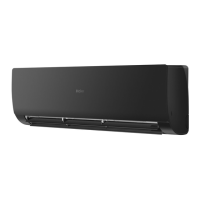
Wall Mounted Type DC Inverter
221
Af12Ab1Hra
221
Introduction
223
Model Name Explanation (DC Inverter)
223
Caution in Repair (DC Inverter)
224
Safety Cautions (DC Inverter)
224
Features (DC Inverter)
229
Specifications (DC Inverter)
230
Sensors List
231
Piping Diagrams (DC Inverter)
232
Printed Circuit Board Connector Wiring Diagram (DC Inverter)
233
Automatic Operation (DC Inverter)
236
Cooling Operation Mode (DC Inverter)
236
Functions and Control (DC Inverter)
236
Dehumidifying Mode
237
Heating Operation Mode
237
Strength Operation
238
Air Refreshing (DC Inverter)
239
Dormant Operation (DC Inverter)
239
Mute Operation (DC Inverter)
239
Timing (DC Inverter)
239
Low Load Protection Control (DC Inverter)
240
Urgent On/Off Input (DC Inverter)
240
Abnormal Operation of Indoor System (DC Inverter)
241
Abnormality Confirmation Approaches (DC Inverter)
241
High Load Protection Control (DC Inverter)
241
Malfunction List Resume (DC Inverter)
241
Fixed Frequency Operation (DC Inverter)
242
Power Cut Compensation (DC Inverter)
242
Single Indoor System Operation (DC Inverter)
242
Transmission Abnormality (DC Inverter)
242
Test Program (DC Inverter)
243
The Control System of Outdoor Unit (DC Inverter)
243
The Operation Frequency of Outdoor Unit and Its Control (DC Inverter)
243
Time Cutting Function (DC Inverter)
243
Value of Thermistor (DC Inverter)
244
System Configuration (DC Inverter)
247
Parts and Functions (DC Inverter)
248
Emergency Operation and Test Operation
249
Parts and Functions Operation
249
Air Flow Direction Adjustment (DC Inverter)
250
Timer On/Off Operation (DC Inverter)
250
Power/Quiet Operation (DC Inverter)
251
Sleep Operation (DC Inverter)
251
Indoor Unit Installation (DC Inverter)
252
Drawing of Pipe (DC Inverter)
253
Fixing the Indoor Unit Body (DC Inverter)
253
Removal of Front Grille (DC Inverter)
253
Removing the Wiring Cover (DC Inverter)
253
Check for Installation and Test Run (DC Inverter)
254
Cutting and Flaring Work of Piping (DC Inverter)
254
On Drainage (DC Inverter)
254
Power Source Installation (DC Inverter)
254
Maintenance (DC Inverter)
255
Troubleshooting (DC Inverter)
257
Center of Gravity (DC Inverter)
258
Dimensional Drawings (DC Inverter)
258
Parameter of Primary Electronic Appliance (DC Inverter)
259
Problem Symptoms and Measures (DC Inverter)
259
Service Diagnosis (DC Inverter)
259
Error Codes and Description (DC Inverter)
260
Thermistor or Related Abnormality (DC Inverter)
261
Circuit Diagrams (DC Inverter)
275
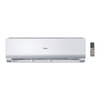
Model No. AS07NS3HRA / AS09NS3HRA
276
Wall Mounted Type
276
Introduction
278
Features
284
Specifications
285
Sensors List
286
Piping Diagrams
287
Printed Circuit Board Connector Wiring Diagram
288
Functions and Control
291
System Configuration
302
Conter of Gravity
310
Dimensional Drawings
310
Service Diagnosis
311
Circuit Diagrams
327
As07\09Ns3Hra
276
Model No. AS15NS3HRA
328
Introduction
330
Features
336
Specifications
337
Sensors List
338
Piping Diagrams
339
Printed Circuit Board Connector Wiring Diagram
340
Functions and Control
343
System Configuration
354
Conter of Gravity
362
Dimensional Drawings
362
Service Diagnosis
363
Circuit Diagrams
379
Model No. AS18NS3HRA
380
Introduction
382
Features
388
Specifications
389
Sensors List
390
Piping Diagrams
391
Printed Circuit Board Connector Wiring Diagram
392
Functions and Control
395
System Configuration
406
Conter of Gravity
414
Dimensional Drawings
414
Service Diagnosis
415
Circuit Diagrams
431
Model No. AS24NS3HRA
432
Introduction
434
Features
440
Specifications
441
Sensors List
442
Piping Diagrams
443
Printed Circuit Board Connector Wiring Diagram
444
Functions and Control
447
System Configuration
458
Conter of Gravity
466
Dimensional Drawings
466
Service Diagnosis
467
Circuit Diagrams
483
5
Based on 1 rating
Ask a question
Give review
Questions and Answers:
Need help?
Do you have a question about the Haier Super Match 3U24GS2ERA and is the answer not in the manual?
Ask a question
Haier Super Match 3U24GS2ERA Specifications
General
Brand
Haier
Model
Super Match 3U24GS2ERA
Category
Air Conditioner
Language
English
Related product manuals
Haier Super Match Series
483 pages
Haier Super Match AF12AS1ERA
483 pages
Haier Super Match AB24ES1ERA
483 pages
Haier SUPER MATCH AS20S2SF2FA
53 pages
Haier SUPER MATCH AS25S2SF1FA-BC
54 pages
SUPER MATCH AS12NS1HRA-GOLDEN
60 pages
Haier MRV5
36 pages
Haier MRV II
147 pages
Haier MRV S II
88 pages
Haier MRV Series
72 pages
Haier AS20S2SF1FA-MB
233 pages
Haier Arctic Multi Series
3 pages
 Loading...