3 - Description
19
CycloneFilter
With the CycloneFilter any impurities in the spray liquid will by-pass the
filter and be re-circulated back to the tank via the return flow.
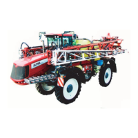
Function diagram
1. Filter lid
2. From pump
3. To boom
4. Return to tank
5. Return valve
Valve (5) has three positions marked with small dots on the lever:
A. This position marked with 1 dot: There is no return flow. Position is
used when rinsing the boom if there is spray liquid in the main
tank. Also used when high spraying volume is required.
B. This position marked with 2 dots: Normal spraying position. With
return flow to prevent filter is going to be clogged when spraying.
This position is used when rinsing the boom if the main tank is empty.
C. This position marked with 3 dots: Flushing position which is used if filter is clogged. Lift and hold the lever to use this
position which largely increases return flow and flushes the filter. The pressure SmartValve must be set to “Spraying”.
μ
ATTENTION! Use of position C is no guarantee for a clean filter. Always regularly do a visual inspection and cleaning
of the filter. If necessary see “10 Hours Service - CycloneFilter” on page 80.
€
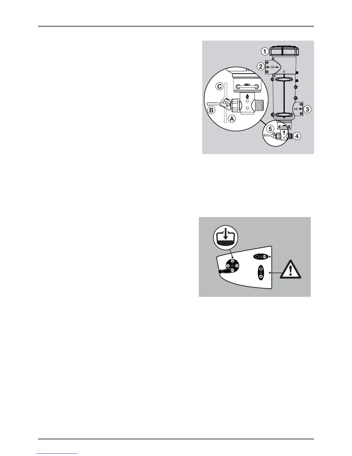
DANGER! Never open the Cyclone filter unless the suction
valve is closed and the pressure SmartValve is turned to “Main
tank”. Otherwise, spraying liquid may hit you when opening
the filter, and drain from the main tank!
 Loading...