3. Parameter setting
3-33
You can arrange the input contact point in multiple arrangements so that other pins can have the
same function.
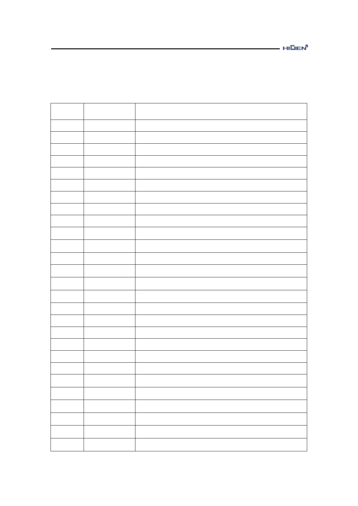
[ Input contact point function table ]
Do not use applicable input pin
Servo on/off operation input contact point
When the control mode is multiple mode, control mode conversion
input contact point
Torque/speed/location direction conversion input contact point
P-PI control mode conversion input contact point
Control gain conversion input contact point
Digital torque input contact point 1
Digital torque input contact point 2
Digital torque input contact point 3
Digital speed input contact point 1
/ electronic gear ratio conversion input contact point 1
Digital speed input contact point 2
/ electronic gear ratio conversion input contact point 2
Digital speed input contact point 3
Speed limit use input contact point (Torque control)/
Torque limit use input contact point (Speed, Position control)
CCW revolution limit input contact point(Speed, Position control)/
CCW torque generation limit input contact point(Torque control)
CW revolution limit input contact point(Speed, Position control)/
CW torque generation limit input contact point (Torque control)
Temporary stop input contact point
Emergency stop input contact point
Position command pulse input limit input contact point
Position command pulse clear input contact point
Alarm reset input contact point
Initial data request signal for absolute encoder
Use torque control mode internal setting function
(Can only be entered in P07-01 menu)
Use speed control mode internal setting function
(Can only be entered in P07-01 menu)
Use position control mode internal setting function
(Can only be entered in P07-01 menu)
Use speed/torque multi control mode internal setting function
(Can only be entered in P07-01 menu)
Use speed/position multi control mode internal setting function
(Can only be entered in P07-01 menu)
Use position/torque multi control mode internal setting function
(Can only be entered in P07-01 menu)
 Loading...