PosNo Description Quantity Type
4 Mounting bar 2 -
5 Screw 6 M5x8
6 Side plate 2 -
5.3.3.3 How to reach the rear side of the IED
M11941-2 v5
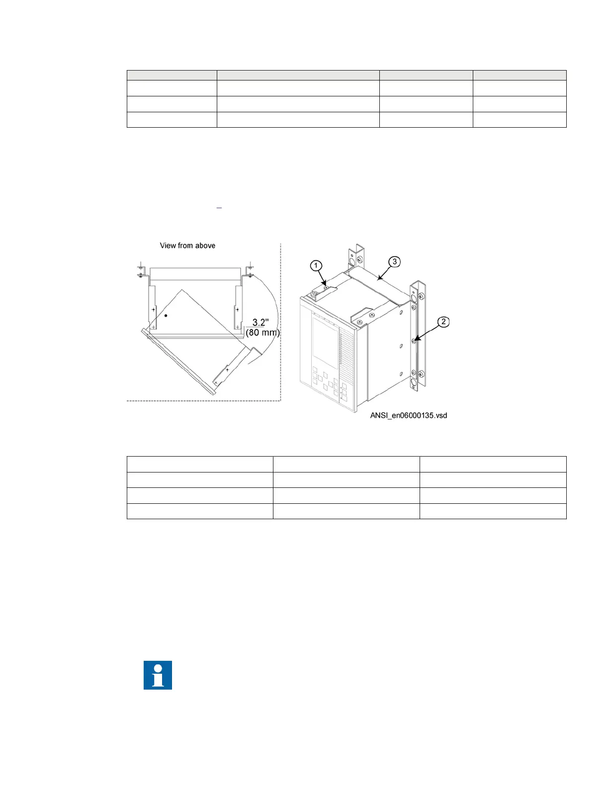
The IED can be equipped with a rear protection cover recommended to be used with this type of
mounting. See figure
6.
To reach the rear side of the IED, a free space of 3.2 inches is required on the unhinged side.
ANSI06000135 V2 EN-US
Figure 6: How to reach the connectors on the rear side of the IED.
PosNo
Description Type
1 Screw M4x10
2 Screw M5x8
3 Rear protection cover (Ordered separately)
5.3.4 Side-by-side 19” rack mounting
IP10323-1 v1
5.3.4.1 Overview
M11974-3 v3
IED case size 1/2 x 19” or 3/4 x 19” and RHGS cases can be mounted side-by-side up to a maximum
size of 19”. For side-by-side rack mounting, the side-by-side mounting kit together with the 19” rack panel
mounting kit must be used. The mounting kit has to be ordered separately.
Use only the screws included in the mounting kit when mounting the plates and the angles on
the IED. Screws with wrong dimension may damage the PCBs inside the IED.
1MRK514026-UUS Rev. P Section 5
Mounting
670 series 25
Installation manual
© 2017 - 2023 Hitachi Energy. All rights reserved
 Loading...


