2.3.1 Requirements
a) The RS485 specification requires the Signal A and Signal B wires.
b) Each node also requires (5 V) Excitation of the RS485 termination network.
c) Vim - the common mode voltage between any pair of RS485 chips may not exceed 10
V.
d) A physical ground connection between all RS485 circuits will reduce noise.
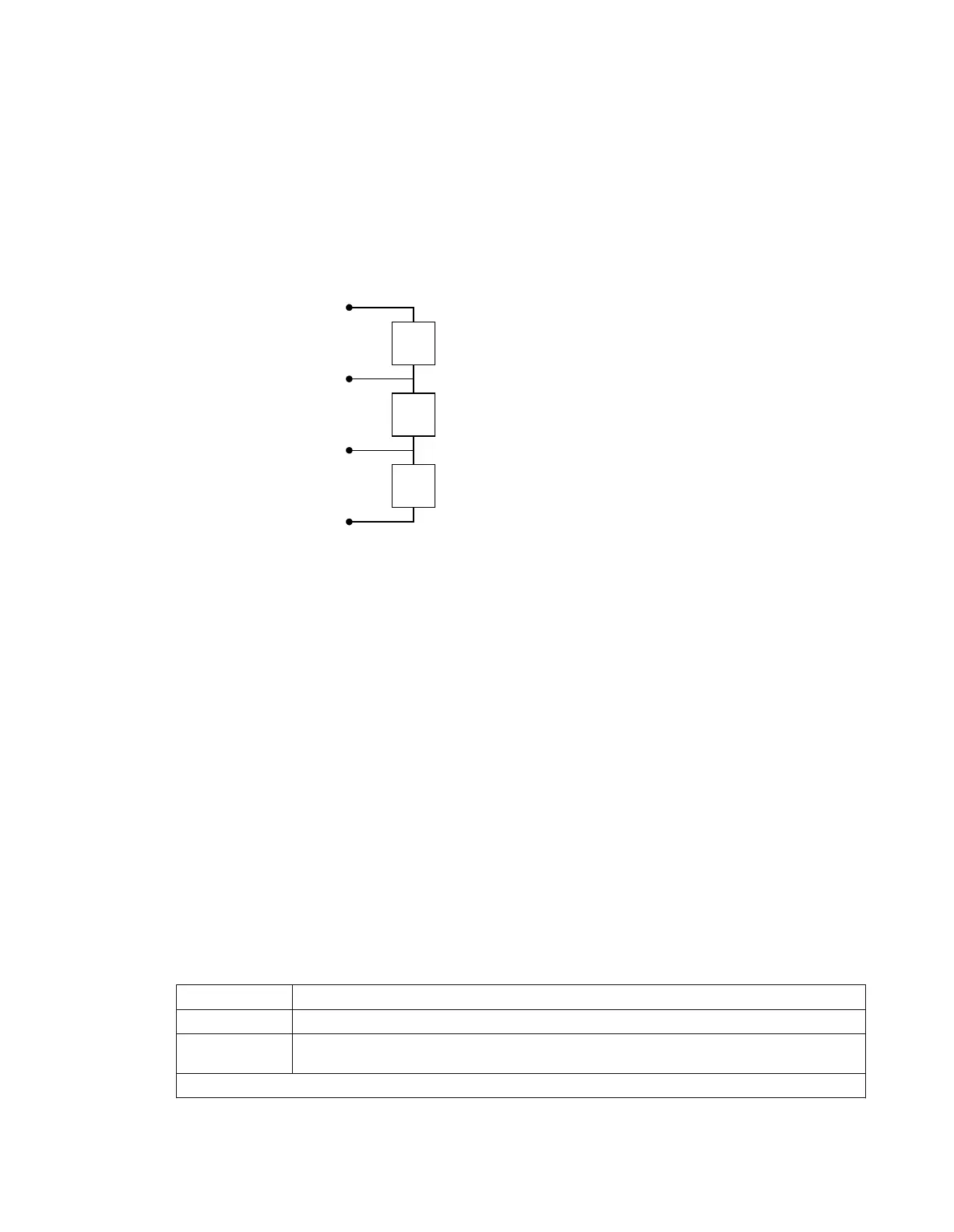
2.3.2 Bus segment termination network
The termination network below required at each end of each Bus Ph-segment.
en03000112.vsd
ExV+
Signal B
Signal A
DGND
Ru = 390 ohm
1/4 W, 2%
Rt = 220 ohm
1/4 W, 2%
Rd = 390 ohm
1/4 W, 2%
ExV is supplied by the Node at end of the Bus Segment
IEC03000112 V1 EN-US
Figure 47: RS-485 bus segment termination
ExV is supplied by the Node at end of the Bus Segment
The specifications of the components are:
a) Ru + 5 V to Signal B = 390 W, 0.25 W ±2.5%
b) Rt Signal B to Signal A = 220 W, 0.25 W ±2.5%
c) Rd Signal A to GND = 390 W, 0.25 W ±2.5%
2.3.3 Bus power distribution
The end node in each Ph-segment applies 5 V bus excitation power to the Termination network via
the Excitation pair (ExV+ and GND) used in the Type 3 Physical layer specification.
6.4.3 Data on RS485 serial communication module cable
SEMOD176342-280 v2
Type:
Twisted-pair S-STP (Screened – Screened Twisted Pair)
Shield: Individual foil for each pair with overall copper braid
Length: Maximum 1200 m (3000 ft) from one system ground to the next system ground (includes length from
platform point to system ground on both sides)
Table continues on next page
Section 6 1MRK514026-UUS Rev. P
Connecting
72 670 series
Installation manual
© 2017 - 2023 Hitachi Energy. All rights reserved
 Loading...


