SEMOD53376-2 v6
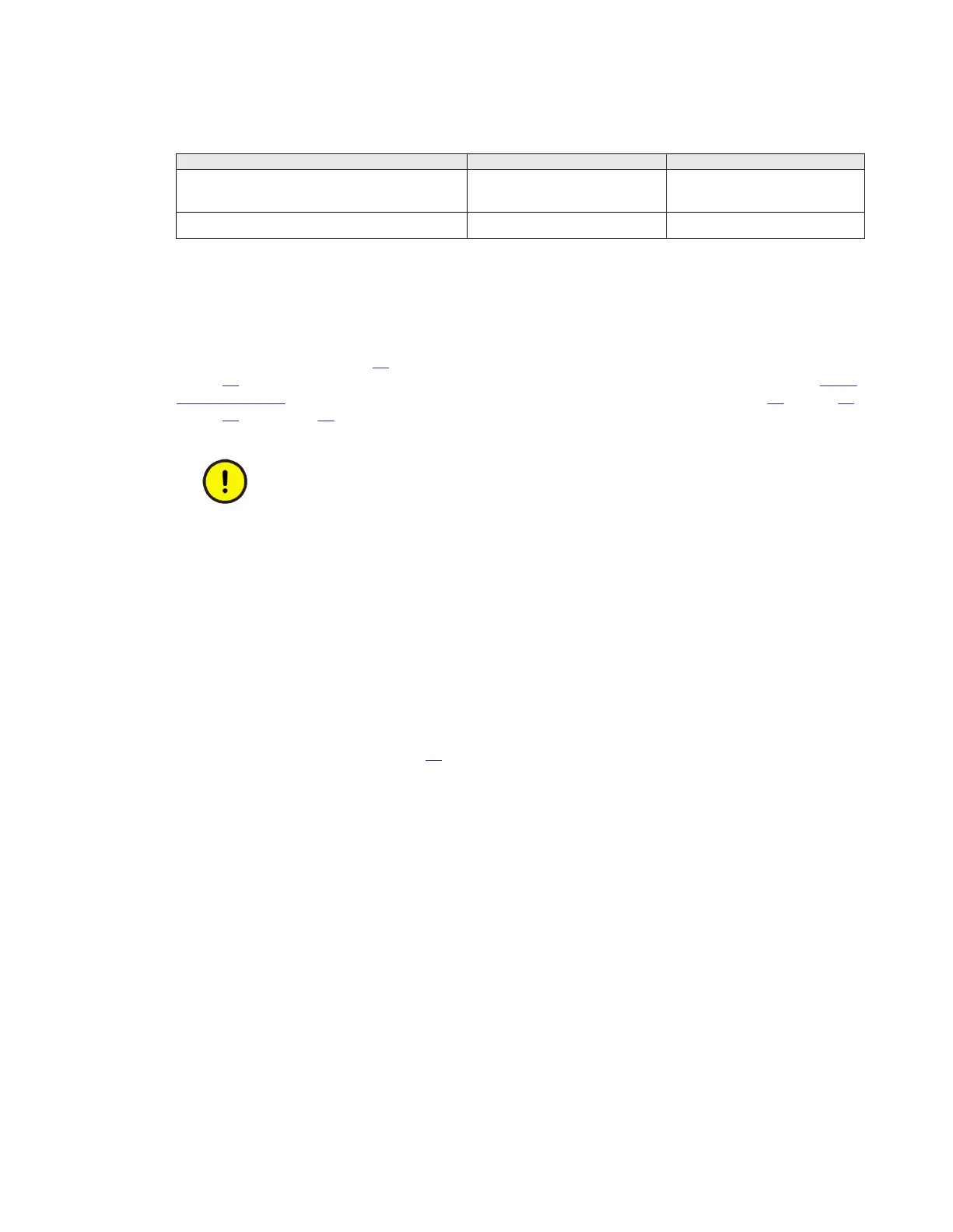
Table 9: CT and VT circuit connectors
Connector type Rated voltage and current Maximum conductor area
Screw compression type 250 V AC, 20 A
4 mm
2
(AWG12)
2 x 2.5 mm
2
(2 x AWG14)
Terminal blocks suitable for ring lug terminals 250 V AC, 20 A
4 mm
2
(AWG12)
6.1.5 Connecting the binary input and output signals
M11992-9 v8
Auxiliary power and signals are connected using voltage connectors. Signal wires are connected to a
female connector (see Figure 29) which is then plugged into the corresponding male connector (see
Figure
30) located at the rear of the IED. For location of BIM, BOM, SOM and IOM refer to section "Rear
side connectors". Connection diagrams for BIM, BOM, SOM and IOM are shown in Figure 17, Figure 21,
Figure 22 and Figure 23.
Do not insert anything else to the female connector but the corresponding male connector.
Inserting anything else (such as a measurement probe) may violate the female connector and
prevent a proper electrical contact between the printed circuit board and the external wiring
connected to the screw terminal block.
If the IED is equipped with a test-switch of type RTXP 24, COMBIFLEX wires with 20 A sockets, 1.5mm²
(AWG16) conductor area must be used to connect the auxiliary power.
Procedure
1. Connect signals to the female connector
The conductors can be of rigid type (solid, stranded) or of flexible type.
The female connectors accept conductors with a cross section area of 0.2-2.5 mm
2
(AWG 24-14). If
two conductors are used in the same terminal, the maximum permissible cross section area is 0.2-1
mm
2
(AWG 24-18).
If two conductors, each with area 1.5 mm
2
(AWG 16) need to be connected to the same terminal, a
ferrule must be used, see figure
31. Crimp this ferrule properly to the wire using tools as
recommended by the supplier of the ferrules (keep stripping length of the cable to minimum 10
mm). The fastening screw shall be tightened with a torque of 0.4 Nm (This torque applies to all
binary connectors).
2. Plug the female connector to the corresponding back-side mounted male connector
3. Lock the female connector by fastening the lock screws
Section 6 1MRK514026-UUS Rev. P
Connecting
50 670 series
Installation manual
© 2017 - 2023 Hitachi Energy. All rights reserved
 Loading...


