1MRK002556-BA-2-PG V2 EN-US
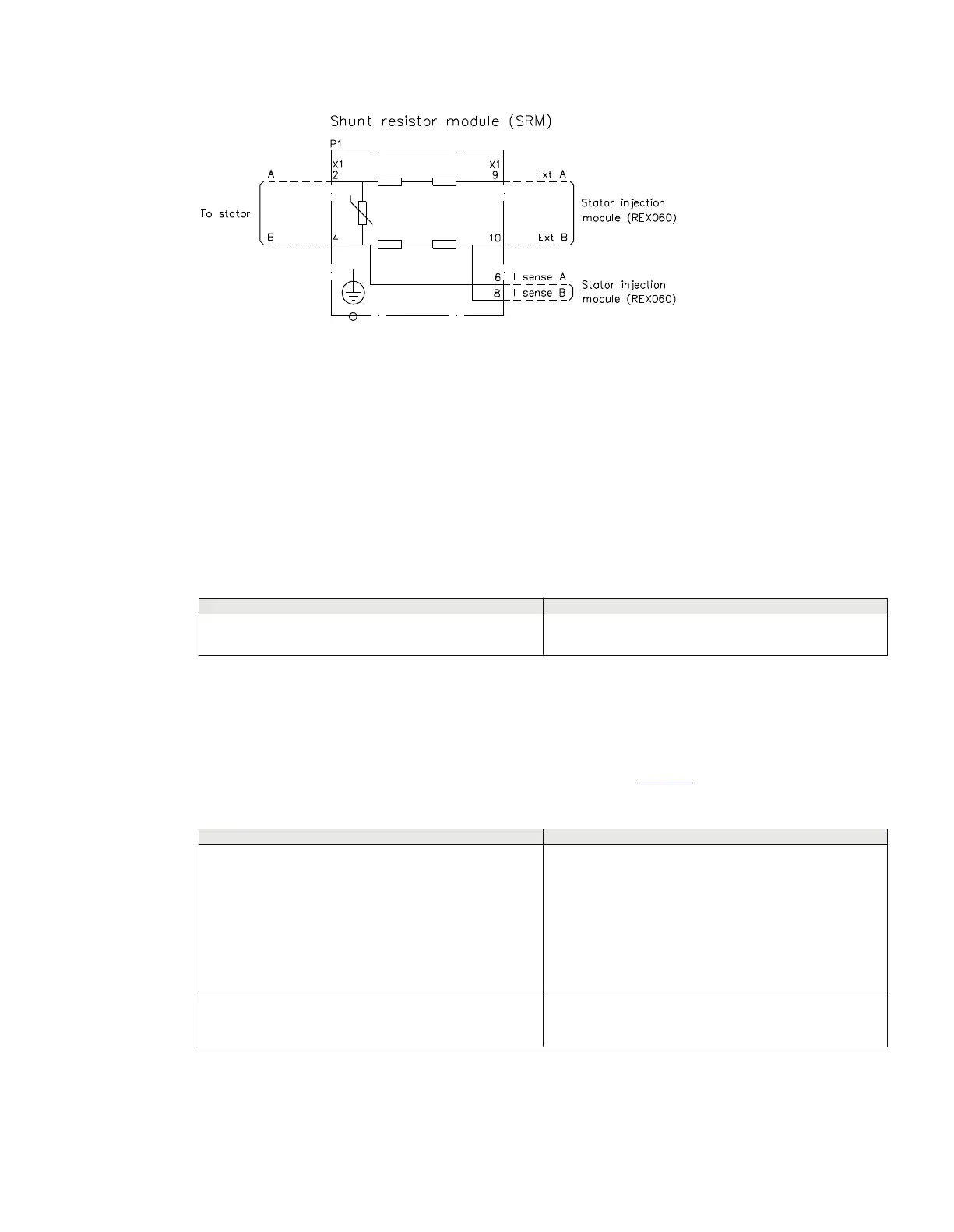
Figure 40: Shunt resistor module
6.2.2 Connecting injection unit REX060, coupling capacitor unit REX061
and shunt resistor unit REX062 and Signal Injection Transformer
SIT
GUID-0B6A1CDE-9CDE-413C-9E85-9314175D901E v6
The injection unit REX060 should be installed close to the IED in the same cubicle, or at maximum within
10 m distance from the IED.
Table 11: Guidelines for connection cables between REG670 and REX060
Location
Guideline
Wiring inside the protection cubicle Dedicated two-core cable with cross section at least 1.5
mm
2
.
The coupling capacitor unit REX061 should be mounted close to the generator in order to limit the
exposure of the field circuit. The protective earthing point (PE) of the REX061 case shall be earthed to
the same earth of the generator. REX061 is typically installed in the excitation cubicle if the cubicle is
close to the generator. REX061 should be connected as a permanently connected equipment. The wiring
of REX061 should be carried out according to the guidelines in the
Table 12.
Table 12: Guidelines for connection cables for REX061
Location
Guideline
Between REX060 and REX061
Shielded twisted pair cable with cross section 1.5 mm
2
(or
14 AWG), lay length not longer than 71 mm, coverage of
the shield at least 85%, rated voltage at least 600 V AC
and voltage test at least 2 kV AC for 5 minutes. The cable
UL2586-SB TEW 2X14AWG(41/0.26)LF by Hitachi or an
equivalent cable shall be used. The installation of this cable
shall be according to a proper EMC design, considering
that it is a measurement cable with low current and low
voltage signals.
Between REX061 and field winding
This cable should have cross section of at least 1.5 mm
2
and its rated voltage should be selected according to the
excitation system ceiling voltage.
1MRK514026-UUS Rev. P Section 6
Connecting
670 series 59
Installation manual
© 2017 - 2023 Hitachi Energy. All rights reserved
 Loading...


