necessary, it must be possible to disconnect manually from the power supply. A fuse or circuit breaker up
to 6 A and 250 V should be close to the equipment. It is recommended to separate the instrument
transformer leads from the other cables, that is, they should not be run in the same cable ducts or loom.
The connections are made on connector X11.
6.1.4 Connecting to CT and VT circuits
M11991-6 v3
CTs and VTs are connected to the 24–pole connector of the Transformer input module (TRM) on the rear
side of the IED. Connection diagram for TRM is shown in figure
16.
Use a solid conductor with a cross section area between 2.5-6 mm
2
(AWG14-10) or a stranded
conductor with a cross section area between 2.5-4 mm
2
(AWG14-12).
If the IED is equipped with a test-switch of type RTXP 24, COMBIFLEX wires with 20 A sockets must be
used to connect the CT and VT circuits.
M11991-10 v4
Connectors on TRM (for location see section
"Rear side connectors") for current and voltage transformer
circuits are so called “feed-through IED blocks” and are designed for conductors with cross sectional
area up to 4 mm
2
(AWG 12). The screws used to fasten the conductors should be tightened with a torque
of 1Nm.
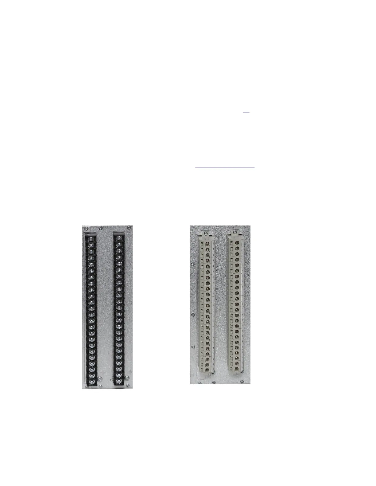
Connector terminals for CT and VT circuits, as well as terminals for binary input and output signals, can
be of either ringlug or compression connection type, depending on ANSI/IEC standards, or customers
choice.
IEC06000505 V1 EN-US
Figure 27: Examples of ringlug
terminals
IEC06000506 V1 EN-US
Figure 28: Examples of standard
compression connection
terminals
1MRK514026-UUS Rev. P Section 6
Connecting
670 series 49
Installation manual
© 2017 - 2023 Hitachi Energy. All rights reserved
 Loading...


