IEC06000168 V3 EN-US
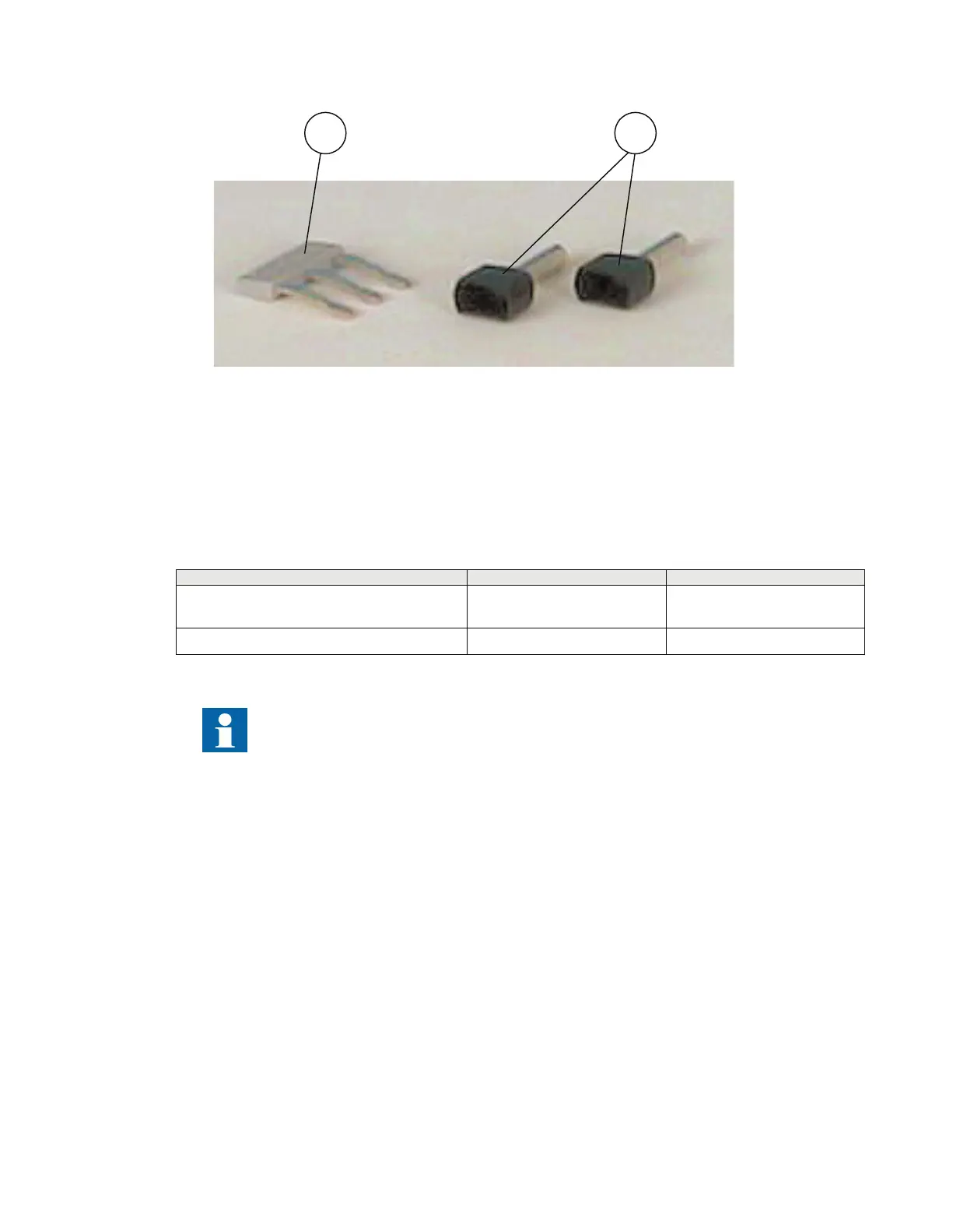
Figure 31: Accessories
PosNo Description
1 Ferrule
2 Bridge connector, used to jump terminal points in a connector.
M12583-1 v8
Table 10: Auxiliary power supply and binary I/O connectors
Connector type
Rated voltage Maximum conductor area
Screw compression type 250 V AC
2.5 mm
2
(AWG14)
2 × 1 mm
2
(2 x AWG18)
Terminal blocks suitable for ring lug terminals 300 V AC
3 mm
2
(AWG14)
Because of limitations of space, when ring lug terminal is ordered for Binary I/O connections,
one blank slot is necessary between two adjacent I/O modules. Please refer to the ordering
particulars for details.
6.1.6 Making the shield connection
M11998-3 v6
When using shielded cables, always make sure that the shields are connected according to applicable
engineering methods.
Section 6 1MRK514026-UUS Rev. P
Connecting
52 670 series
Installation manual
© 2017 - 2023 Hitachi Energy. All rights reserved
 Loading...


