Protective conductor terminal must be connected to the cubicle and generator protective grounding grid.
Electrical codes and standards require that protective ground cables are green/yellow conductors with a
cross section area of at least 2.5 mm
2
(AWG 14). The cubicle must be properly connected to the
generator grounding grid. Use a conductor with a core cross section area of at least 4 mm
2
(AWG 12).
The protective grounding terminal is also the functional ground terminal. The functional ground is the
reference for rotor injection and measurement. The connection to the generator grounding should be as
short and low impedance as possible to reduce unwanted disturbances and improve the quality of rotor
measurements.
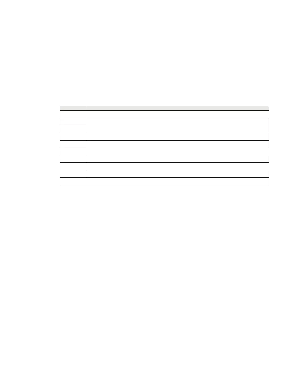
REX062 Shunt resistor unit connections
Table 22: Injection via shunt resistors connection X1
No Signal
1 -
2 Injection
3 -
4 Injection return
5 -
6 Current sense output
7 -
8 Current sense output
9 Injection input, External shunt
10 Injection input return, External shunt
X1 connector. Connect each signal connector terminal of screw compression type with one 0.14 to 6
mm
2
(AWG 35 - AWG 3) wire or with two 0.14 to 1.5 mm
2
(AWG 35 - AWG 15) wires.
Protective conductor terminal must be connected to the cubicle or station protective grounding system.
Electrical codes and standards require that protective ground cables are green/yellow conductors with a
cross section area of at least 2.5 mm
2
(AWG 14). The cubicle must be properly connected to the station
grounding system. Use a conductor with a core cross section area of at least 4 mm
2
(AWG 12).
6.2.3 Connecting and setting voltage inputs
GUID-BE3E0554-3E96-4489-B8C9-E62953853BB7 v6
The RIM module of REX060 has two analog output channels that shall be connected to two voltage input
channels of the IED. The SIM module of REX060 has two analog output channels that shall be
connected to two voltage input channels of the IED.
If both stator and rotor protections are used, four voltage channels of the IED are required:
• Two IED voltage channels are used for the measured quantities for STTIPHIZ from the SIM module.
• Two more IED voltage channels are used for the measured quantities for ROTIPHIZ from the RIM
module.
1MRK514026-UUS Rev. P Section 6
Connecting
670 series 65
Installation manual
© 2017 - 2023 Hitachi Energy. All rights reserved
 Loading...


