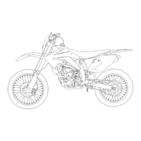
MAINTENANCE
Inspect
and
adjust
the decompressor
CleBrBnCe
while
fhe
engine
is
cold
(be/ow 35"C/95'f).
4-18
DECOMPRESSOR CLEARANCE
INSPECTIONI
ADJUSTMENT
('05 - '07)
Always
inspect and adjust
the
decompressor
clear-
ance after adjusting the r
ight
exhaust valve clear-
ance.
Remove the
following:
- Cylinder head cover (page 9-7)
- Crankshaft hole cap (page 9-8)
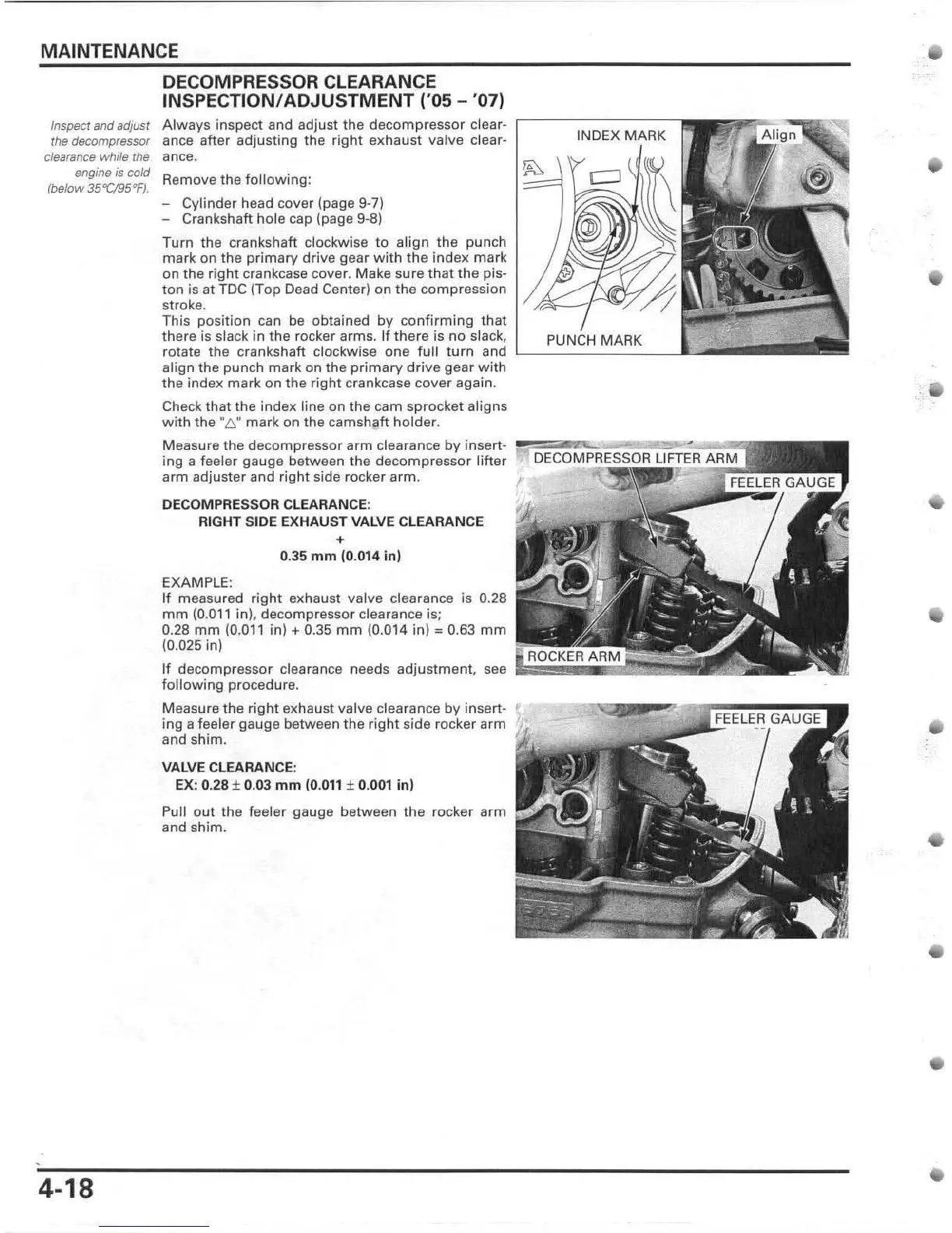
Turn the crankshaft
clockwise to al
ign
the punch
mark on the
primary
drive
gear
wi
th the index
mark
on the right crankcase cover. Make sure
that
the pis-
ton is at
TDC
(T
op
Dead Center)
on
the
compression
stroke.
This
position
can
be
obtained
by
confirming
that
there is slack in the rocker arms. If there is
no
slack,
rolate the crankshaft clockwise
one
full
turn and
align
the punch
mark
on
the
primary
drive
gear
wi
th
the
index
mark
on
the right crankcase cover again.
Check that the index line
on
the cam s
pr
ocket aligns
with
the "6."
mark
on the
camsh~ft
holder.
Meas
ur
e the decompressor
arm
clearance
by
insert-
ing a feeler gauge between the
decompressor
lifter
arm adjuster
and
right side rocker
arm
.
DECQMPRESSQR CLEARANCE:
RIGHT SIDE EXHAUST
VALVE CLEARANCE
+
0.35
mm
(0.014 in)
EXAMPLE:
If measured rig
ht
exhaust valve clearance is 0.28
mm
(0.0
11
in
),
decompressor clearance i
s;
0.28
mm
(0.011 in)
...
0.35
mm
(0.014 in) '" 0.63
mm
(0.025 in)
If
decompressor
clearance needs
adjustment,
see
following
procedure.
Measure the rig
ht
exhaust valve clearance
by
insert-
ing
a feeler gauge between the r
ight
si
de
rocker
arm
and shim.
VALVE
CLEARANCE:
EX
: 0.
28
± 0.
03
mm
(0.
011
± 0.
001
in)
Pull
out
the feeler gauge between the rocker a
rm
and shim.
INDEX MARK
•
•
•
 Loading...