Model 1332A Performance Check
Table
5-2.
Rise Time Specification
d. Displayed trace length shall be 26.3 divisions.
I
Instrument
I
Rise Time
I
Standard
Option 120
Option 121
5-13.
DEFLECTION FACTOR.
A signal with a spec-
ified amplitude applied to
X
AMPLIFIER input shall
cause a 10-division horizontal beam deflection.
A
sig-
nal with a specified amplitude applied to
Y
AMPLI-
FIER input shall cause an &division vertical beam
deflection.
Equipment Required:
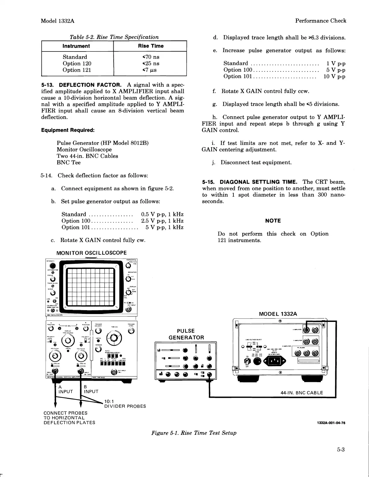
Pulse Generator (HP Model 8012B)
Monitor Oscilloscope
Two 44-in. BNC Cables
BNC Tee
5-14.
Check deflection factor as follows:
a. Connect equipment as shown in figure 5-2.
b. Set pulse generator output as follows:
Standard
.................
0.5
V
p-p,
1
kHz
Option 100.
...............
2.5
V
p-p,
1
kHz
Option 101
..................
5
V
p-p,
1
kHz
c. Rotate
X
GAIN control fully cw.
MONITOR OSCILLOSCOPE
e. Increase pulse generator output as follows:
..........................
Standard
1
V
p-p
Option 100.
........................
5
V
p-p
......................
Option 101.. 10
V
p-p
f. Rotate
X
GAIN control fully ccw.
g. Displayed trace length shall be
65 divisions.
h. Connect pulse generator output to
Y
AMPLI-
FIER input and repeat steps b through
g
using
Y
GAIN control.
i. If test limits are not met, refer to
X-
and
Y-
GAIN centering adjustment.
j.
Disconnect test equipment.
5-15.
DIAGONAL SETTLING TIME.
The
CRT
beam,
when moved from one position to another, must settle
to within
1
spot diameter in less than 300 nano-
seconds.
NOTE
Do not perform this check on Option
121 instruments.
MODEL 1332A
1
INPUT
1
INPUT
1O:l
DIVIDER PROBES
CONNECT PROBES
TO HORIZONTAL
DEFLECTION PLATES
Figure
5-1.
Rise Time Test Setup
Scans by ArtekMedia © 2008
 Loading...


