Model 1332A
BACK
Performance Check
MONITOR OSCILLOSCOPE
(FRONT AND BACK)
-
I
UUUVVVUU
J
44-IN. BNC CABLE
I
FRONT
PULSE GENERATOR
MODEL
1332A
\
0
..".".,E.
@
I
44-IN.
BNC
CABLE
44-IN.
BNC CABLE
1332~-004-06-76
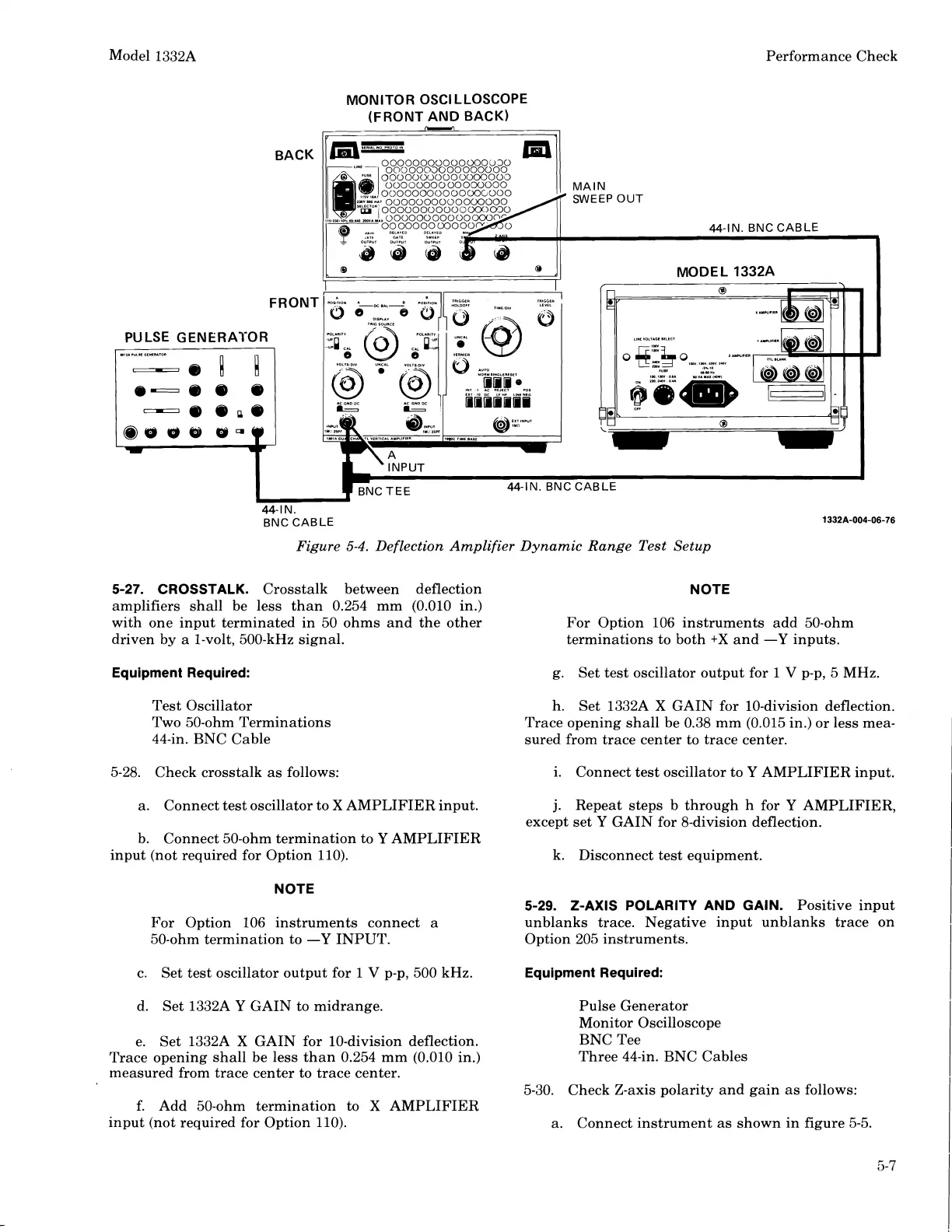
Figure
5-4.
Deflection Amplifier Dynamic Range Test Setup
5-27.
CROSSTALK.
Crosstalk between deflection
NOTE
amplifiers shall be less than 0.254 mm (0.010 in.)
with one input terminated in 50 ohms and the other For Option 106 instruments add 50-ohm
driven by a 1-volt, 500-kHz signal. terminations to both
+X
and
-Y
inputs.
Equipment Required:
g. Set test oscillator output for
1
V
p-p, 5 MHz.
Test Oscillator
Two
50-ohm Terminations
44-in. BNC Cable
h.
Set
1332A
X
GAIN for 10-division deflection.
Trace opening shall be 0.38 mm (0.015 in.) or less mea-
sured from trace center to trace center.
5-28. Check crosstalk as follows: i. Connect test oscillator to
Y
AMPLIFIER input.
a. Connect test oscillator to
X
AMPLIFIER input.
j.
Repeat steps b through h for
Y
AMPLIFIER,
except set
Y
GAIN for 8-division deflection.
b. Connect 50-ohm termination to
Y
AMPLIFIER
input (not required for Option 110). k. Disconnect test equipment.
NOTE
5-29.
Z-AXIS POLARITY AND GAIN.
Positive input
For Option 106 instruments connect a unblanks trace. Negative input unblanks trace on
50-ohm termination to
-Y
INPUT.
Option 205 instruments.
c. Set test oscillator output for 1
V
p-p, 500 kHz.
Equipment Required:
d. Set 1332A
Y
GAIN to midrange. Pulse Generator
Monitor Oscilloscope
e. Set
1332A
X
GAIN for 10-division deflection. BNC Tee
Trace opening shall be less than 0.254 mm (0.010 in.)
Three 44-in. BNC Cables
measured from trace center to trace center.
5-30. Check Z-axis polarity and gain as follows:
f. Add
50-ohm termination to
X
AMPLIFIER
input (not required for Option 110).
a. Connect instrument as shown in figure 5-5.
Scans by ArtekMedia © 2008
 Loading...


