Performance Check
BNC
TEE
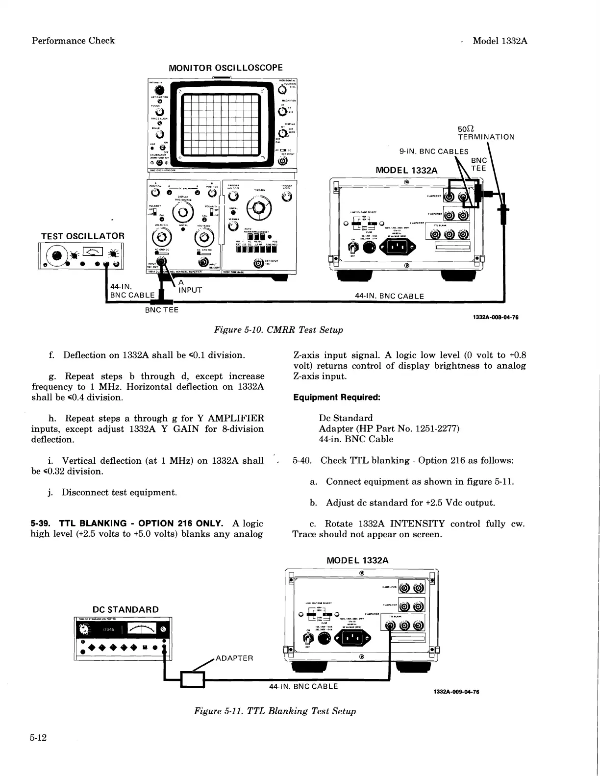
Figure
5-10.
CMRR
Test Setup
f.
Deflection on
1332A shall be s0.1 division. Z-axis input signal. A logic low level (0 volt to t0.8
volt) returns control of display brightness to analog
g. Repeat steps b through d, except increase Z-axis input.
frequency to
1
MHz. Horizontal deflection on 1332A
shall be 60.4 division.
Equipment Required:
h. Repeat steps a through g for Y AMPLIFIER
Dc Standard
inputs, except adjust
1332A Y GAIN for 8-division
Adapter (HP Part No. 1251-2277)
deflection. 44-in. BNC Cable
i. Vertical deflection (at
1
MHz) on 1332A shall
,
5-40. Check TTL blanking
-
Option 216 as follows:
be 60.32 division.
a.
Connect equipment as shown in figure 5-11.
j.
Disconnect test equipment.
b. Adjust dc standard for
+2.5 Vdc output.
5-39.
TTL BLANKING
-
OPTION 216 ONLY.
A logic c. Rotate 1332A INTENSITY control fully cw.
high level
(t2.5 volts to t5.0 volts) blanks any analog
Trace should not appear on screen.
MODEL
1332A
1332A-009-04-76
Figure
5-11.
TTL Blanking Test Setup
Scans by ArtekMedia © 2008
 Loading...


