Performance Check
Model
1332A
b. Rotate
X
POSITION control fully ccw. Beam
should go off screen to left.
NOTE
If a capacitance bridge is used, special
care must be taken to null out capacitance
of connecting cable and to null out the
effect of the
1
megohm input resistance.
c. With no input to
Y
amplifier, rotate
Y
POSI-
TION control fully cw. Beam should move upward
and off screen.
d. Rotate
Y
POSITION control fully ccw. Beam
should move downward and off screen.
5-25.
DEFLECTION AMPLIFIER DYNAMIC RANGE.
The dynamic range shall extend to at least 1/2 screen
diameter beyond full screen.
5-21.
INPUT RESISTANCE.
Measure input resist-
ance of
X,
Y,
and
Z
amplifiers.
Equipment Required:
Equipment Required:
Pulse Generator (HP Model 8012B)
Monitor Oscilloscope
BNC Tee
Three 44-in. BNC Cables
5-22. Check input resistance as follows:
a. Measure each input resistance with ohmmeter
leads connected positive-negative and then
negative-
positive and take average of both readings.
5-26. Check deflection amplifier dynamic range as
follows:
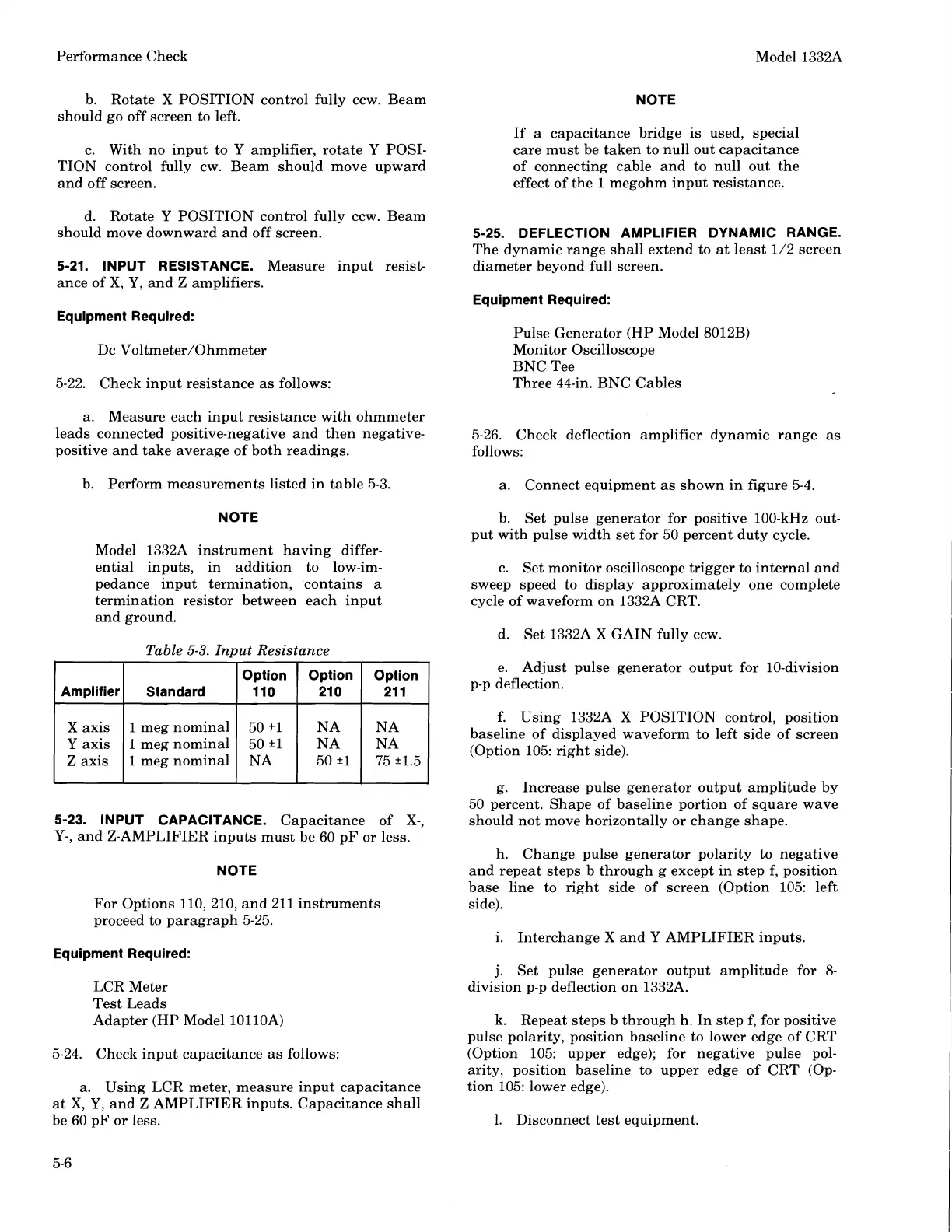
b. Perform measurements listed in table 5-3.
a. Connect equipment as shown in figure 5-4.
NOTE
b.
Set pulse generator for positive 100-kHz out-
put with pulse width set for 50 percent duty cycle.
Model
1332A instrument having differ-
ential inputs, in addition to
low-im-
pedance input termination, contains a
termination resistor between each input
and ground.
c. Set monitor
oscilloscove trigger to internal and
--
sweep speed to display approximately one complete
cycle of waveform on
1332A CRT.
d. Set
133212
X
GAIN fully ccw.
Table
5-3.
Input Resistance
e. Adjust pulse generator output for 10-division
p-p deflection.
Option
110
Option
I
Option
21 0 21 1
Amplifier
Standard
X
axis
Y
axis
Z
axis
1
meg nominal
1 meg nominal
1 meg nominal
f. Using
1332A
X
POSITION control, position
baseline of displayed waveform to left side of screen
(Option 105: right side).
g. Increase pulse generator output amplitude by
50 percent. Shape of baseline portion of square wave
should not move horizontally or change shape.
5-23.
INPUT CAPACITANCE.
Capacitance of
X-,
Y-,
and Z-AMPLIFIER inputs must be 60 pF or less.
h. Change pulse generator polarity to negative
and repeat steps b through g except in step
f, position
base line to right side of screen (Option 105: left
side).
NOTE
For Options 110, 210, and 211 instruments
proceed to paragraph 5-25.
i. Interchange
X
and
Y
AMPLIFIER inputs.
Equipment Required:
j.
Set pulse generator output amplitude for
8-
division p-p deflection on 1332A.
LCR Meter
Test Leads
Adapter (HP Model
10110A)
k. Repeat steps b through h. In step f, for positive
pulse polarity, position baseline to lower edge of CRT
(Option 105: upper edge); for negative pulse pol-
arity, position baseline to upper edge of CRT (Op-
tion 105: lower edge).
5-24. Check input capacitance as follows:
a.
Using LCR meter, measure input capacitance
at
X,
Y,
and
Z
AMPLIFIER inputs. Capacitance shall
be 60
pF or less.
1. Disconnect test equipment.
Scans by ArtekMedia © 2008
 Loading...


