Adjustments Model 1332A
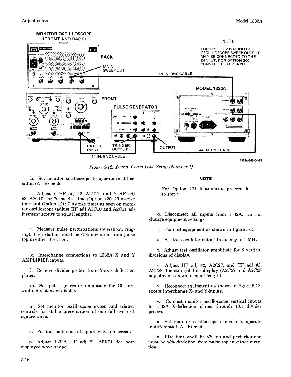
MONITOR OSCILLOSCOPE
(FRONT AND BACK)
I"
-
7
NOTE
r
II
FOR
OPTION
205
MONITOR
44-IN. BNC
-
:
CABL
-
OSCILLOSCOPE
SWEEP
OUTPUT
MAY
BE CONNECTED TO THE
Z-INPUT, FOR OPTION
206
CONNECT TO-LTZ INPUT
1
MODEL 1332A
1
PULSE GENERATOR
44-IN. BNC
CABLE
1332A-010-04-76
Figure
5-12.
X-
and Y-axis Test Setup (Number
1)
h. Set monitor oscilloscope to operate in differ-
NOTE
ential (A-B) mode.
For Option 121 instrument, proceed to
i. Adjust Y HF adj #2,
A2Cl1, and
Y
HF adj
to step v.
#3,
A2C10, for
70
ns rise time (Option 120: 25 ns rise
time and Option 121: 7
ps rise time) as seen on moni-
tor oscilloscope (adjust HF adj
A2C10 and A2Cll ad-
justment screws to equal lengths). q. Disconnect all inputs from
1332A. Do not
change equipment settings.
j. Measure pulse perturbations (overshoot, ring- r. Connect equipment as shown in figure 5-13.
ing). Perturbation must be
<3% deviation from pulse
top in either direction.
s. Set test oscillator output frequency to
1
MHz.
t. Adjust test oscillator amplitude for
8
vertical
k.
Interchange connections to 1332A X and
Y
divisions of display.
AMPLIFIER inputs.
u. Adjust HF adj #2,
A2C27, and HF adj #3,
1.
Remove divider probes from Y-axis deflection
A2C28, for straight line display (A2C27 and A2C28
plates.
adjustment screws to equal length).
m. Set pulse generator amplitude for 10 hori- v. Reconnect equipment as shown in figure 5-12,
zontal divisions of display.
except interchange
X-
and Y-inputs.
w. Connect monitor oscilloscope vertical inputs
n. Set monitor oscilloscope sweep and trigger to
1332A X-deflection plates through 10:l divider
controls for stable presentation of one full cycle of
probes.
square wave.
x.
Set monitor oscilloscope controls to operate
in differential (A-B) mode.
o. Position both ends of square wave on screen.
y. Rise time shall be
c70 ns and perturbations
p. Adjust
1332A HF adj #1, A2R74, for best must be 63% deviation from pulse top in either direc-
displayed wave shape. tion.
Scans by ArtekMedia © 2008
 Loading...


