Model 1332A
Performance Check
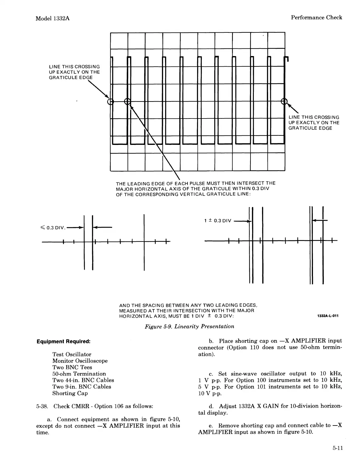
THE LEADING EDGE OF EACH PULSE MUST THEN INTERSECT THE
MAJOR HORIZONTAL
AXIS OF THE GRATICULE WITHIN 0.3 DIV
OF THE CORRESPONDING VERTICAL GRATICULE LINE:
Equipment
Required:
Test Oscillator
Monitor Oscilloscope
Two BNC Tees
50-ohm Termination
Two 44-in. BNC Cables
Two 9-in. BNC Cables
Shorting Cap
AND THE SPACING BETWEEN ANY TWO LEADING EDGES,
MEASURED AT THEIR INTERSECTION
WITH THE MAJOR
HORIZONTAL AXIS, MUST BE
1
DIV
f
0.3 DIV:
Figure
5-9.
Linearity Presentation
b. Place shorting cap on
-X
AMPLIFIER input
connector (Option 110 does not use
50-ohm termin-
ation).
c. Set sine-wave oscillator output to 10 kHz,
1
V
p-p. For Option 100 instruments set to 10 kHz,
5
V
p-p. For Option 101 instruments set to 10 kHz,
10
v
p-p.
5-38. Check CMRR
-
Option 106 as follows: d. Adjust 1332A
X
GAIN for 10-division horizon-
tal display.
a. Connect equipment as shown in figure 5-10,
except do not connect
-X
AMPLIFIER input at this
e. Remove shorting cap and connect cable to
-X
time.
AMPLIFIER input as shown
in
figure 5-10.
Scans by ArtekMedia © 2008
 Loading...


