Model 1332A Performance Check
PULSE GENERATOR
PULSE GENERATOR
..,.A
SULSC
mr"sR..oe
,
,
"~.*IEI
rn*\n
rE"*cn
-e
B
0
r.,
,l,r
,*,
1..
1.71
.UL.IE
*).'T*o*
@-
88
@
P",.C
-@
@DO
I
44-IN.
BNC CABLE
44-IN.
BNC CABLE
I
44-IN.
BNC CABLE
I
1332A-003-04-78
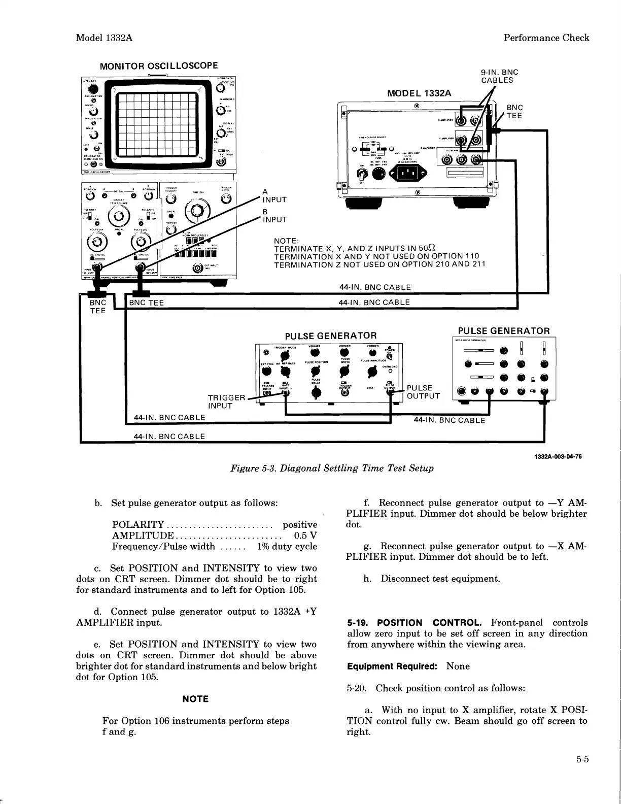
Figure
5-3.
Diagonal Settling Time Test Setup
b. Set pulse generator output as follows: f. Reconnect pulse generator output to -Y AM-
PLIFIER input. Dimmer dot should be below brighter
POLARITY..
......................
positive dot.
AMPLITUDE.
.......................
0.5
V
Frequency/Pulse width
......
1% duty cycle g. Reconnect pulse generator output to -X
AM-
PLIFIER input. Dimmer dot should be to left.
c. Set POSITION and INTENSITY to view two
dots on CRT screen. Dimmer dot should be to right
h. Disconnect test equipment.
for standard instruments and to left for Option 105.
d. Connect pulse generator output to
1332A
+Y
AMPLIFIER input.
e. Set POSITION and INTENSITY to view two
dots on CRT screen. Dimmer dot should be above
brighter dot for standard instruments and below bright
dot for Option 105.
5-19.
POSITION CONTROL.
Front-panel controls
allow zero input to be set off screen in any direction
from anywhere within the viewing area.
Equipment Required:
None
5-20. Check position control as follows:
NOTE
For Option 106 instruments perform steps
f and g.
a. With no input to
X
amplifier, rotate X POSI-
TION control fully cw. Beam should go off screen to
right.
Scans by ArtekMedia © 2008
 Loading...


