Performance Check
Model
1332A
Equipment Required:
Pulse Generator (HP Model 8012B)
Pulse Generator (HP Model 214A)
Monitor Oscilloscope
Three BNC Tees
Five 44-in. BNC Cables
Two 9-in. BNC Cables
5-16. Check diagonal settling time as follows:
symmetry control on HP Model 214A to achieve syn-
chronization between channels A and B.
i. Set HP Model
8012B delay to 10 ns and vernier
cw. Note clean bright dot on lower left of CRT.
j. Turn delay vernier ccw. Note appearance of
distorted trace segment projecting from dot.
k. Adjust delay vernier until length of trace seg-
ment is one dot diameter.
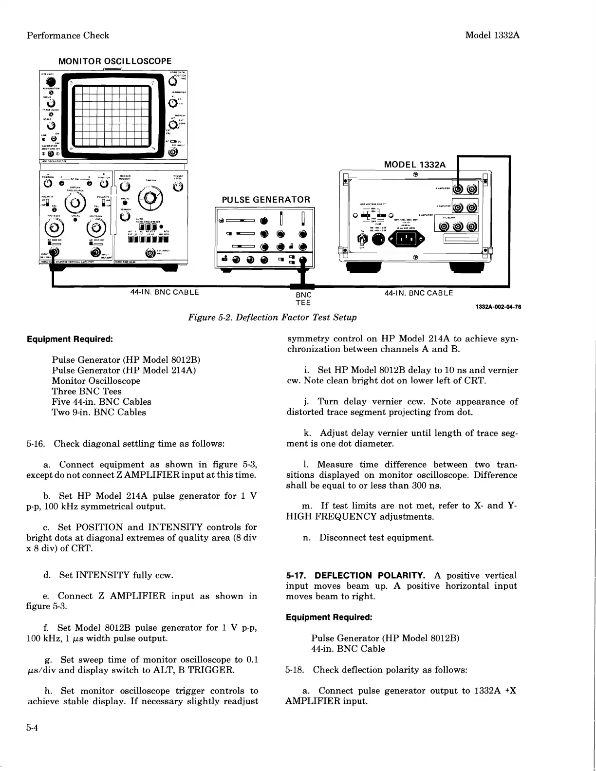
a. Connect equipment as shown in figure 5-3, 1. Measure time difference between two
tran-
except do not connect
Z
AMPLIFIER input at this time. sitions displayed on monitor oscilloscope. Difference
shall be equal to or less than 300 ns.
b. Set HP Model 214A pulse generator for
1
V
p-p, 100 kHz symmetrical output.
m. If test limits are not met, refer to
X-
and
Y-
HIGH FREQUENCY adjustments.
c. Set POSITION and INTENSITY controls for
bright dots at diagonal extremes of quality area (8 div
n. Disconnect test equipment.
x 8 div) of CRT.
d. Set INTENSITY fully ccw.
5-1
7.
DEFLECTION POLARITY.
A positive vertical
input moves beam up. A positive horizontal input
e. Connect
Z
AMPLIFIER input as shown in moves beam to right.
figure 5-3.
Equipment Required:
f.
Set Model 8012B pulse generator for
I
V
p-p,
100 kHz, 1
ps width pulse output. Pulse Generator (HP Model 8012B)
44-in. BNC Cable
g. Set sweep time of monitor oscilloscope to 0.1
ps/div and display switch to ALT, B TRIGGER.
5-18. Check deflection polarity as follows:
h. Set monitor oscilloscope trigger controls to a. Connect pulse generator output to
1332A
+X
achieve stable display. If necessary slightly readjust
AMPLIFIER input.
Scans by ArtekMedia © 2008
 Loading...


