Model 1332A
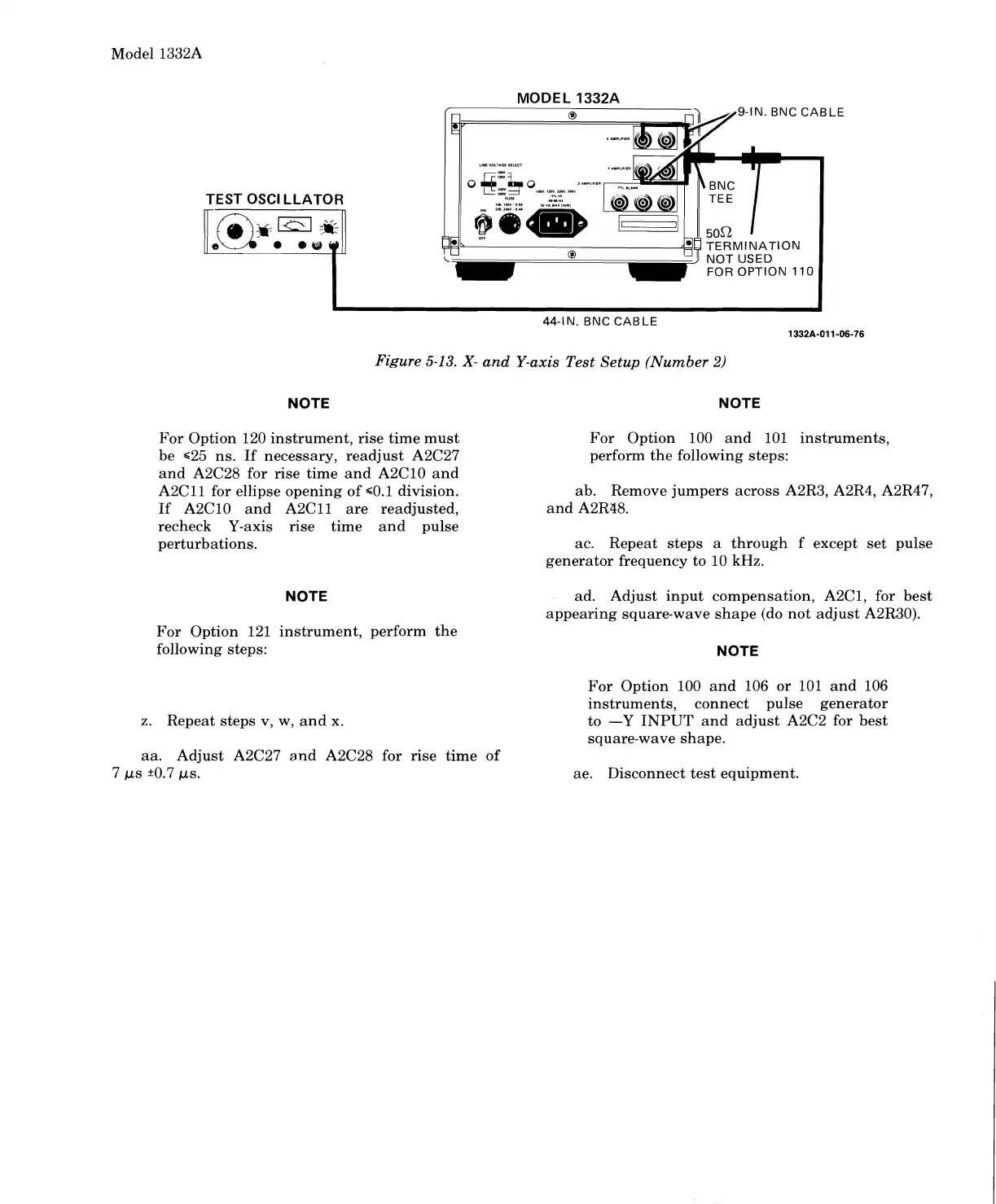
MODEL 1332A
9-IN. BNC CABLE
44-IN. BNC CABLE
1332A-011-06-76
Figure
5-13.
X-
and Y-axis Test Setup (Number
2)
NOTE NOTE
For Option 120 instrument, rise time must For Option 100 and 101 instruments,
be
~25 ns. If necessary, readjust A2C27
perform the following steps:
and
A2C28 for rise time and A2ClO and
A2Cll for ellipse opening of ~0.1 division.
ab. Remove jumpers across
A2R3, A2R4, A2R47,
If A2C10 and A2Cll are readjusted, and A2R48.
recheck Y-axis rise time and pulse
perturbations. ac. Repeat steps a through f except set pulse
generator frequency to 10
kHz.
NOTE
ad. Adjust input compensation, A2C1, for best
appearing square-wave shape (do not adjust
A2R30).
For Option 121 instrument, perform the
following steps:
NOTE
For Option 100 and 106 or 101 and 106
instruments, connect pulse generator
z.
Repeat steps v,
w,
and
x.
to -Y
INPUT
and adjust A2C2 for best
square-wave shape.
aa. Adjust
A2C27 and A2C28 for rise time of
7
ps +0.7 ps. ae. Disconnect test equipment.
Scans by ArtekMedia © 2008
 Loading...


