Performance Check
Model
1332A
MONITOR OSCl LLOSCOPE
(FRONT
AND
BACK)
,ww"""w-"-
30 00000000
3000000000
~~O-oPC_?~2
SWEEP
OUT
(NOT
REQ'D
FOR
OPTION
110)
I
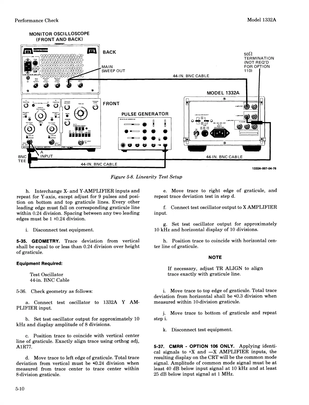
Figure
5-8.
Linearity Test Setup
h. Interchange
X-
and Y-AMPLIFIER inputs and
e. Move trace to right edge of graticule, and
repeat for Y-axis, except adjust for
9
pulses and posi-
repeat trace deviation test in step d.
tion on bottom and top graticule lines. Every other
leading edge must fall on corresponding graticule line
f.
Connect test oscillator output to
X
AMPLIFIER
within 0.24 division. Spacing between any two leading
input.
edges must be 1
i0.24 division.
g.
Set test oscillator output for approximately
i. Disconnect test equipment.
10 kHz and horizontal display of 10 divisions.
5-35. GEOMETRY.
Trace deviation from vertical h. Position trace to coincide with horizontal cen-
shall be equal to or less than 0.24 division over height
ter line of graticule.
of graticule.
NOTE
Equipment Required:
If necessary, adjust TR ALIGN to align
Test Oscillator
trace exactly with graticule line.
44-in. BNC Cable
5-36. Check geometry as follows:
a. Connect test oscillator to
1332A Y AM-
PLIFIER input.
b. Set test oscillator output for approximately
10
kHz and display amplitude of
8
divisions.
c. Position trace to coincide with vertical center
line of graticule. Exactly align trace using orthog adj,
AlR77.
d. Move trace to left edge of graticule. Total trace
deviation from vertical must be
c0.24 division when
measured from trace center to trace center within
8-division graticule.
i. Move trace to top edge of graticule. Total trace
deviation from horizontal shall be
c0.3 division when
measured within 10-division graticule.
j.
Move trace to bottom of graticule and repeat
step i.
k. Disconnect test equipment.
5-37. CMRR
-
OPTION
106
ONLY.
Applying identi-
cal signals to
+X
and
-X
AMPLIFIER inputs, the
resulting display on the CRT will be the common mode
signal. Amplitude of common mode signal must be at
least
40
dB below input signal at 10 kHz and at least
25
dB below input signal at
1
MHz.
Scans by ArtekMedia © 2008
 Loading...


