Model 1332A
d. Rotate 1332A INTENSITY control fully ccw.
Adjustments
NOTE
e. Set dc standard output to t0.8 Vdc.
f. Rotate
1332A INTENSITY control cw. Spot
shall appear on CRT.
g. Disconnect cable from
1332A TTL BLANK-
ING
input.
5-41.
ADJUSTMENTS.
WARNING
Read the Safety Summary at the front
of this manual before performing the
adjustment procedures.
5-42. The following paragraphs describe procedures
to calibrate the instrument so that it will perform
as specified in table 1-1. The entire adjustment pro-
cedure can be done in sequence, or any separate
adjustment can be made by following the steps out-
lined in the appropriate paragraph. However, do not
attempt to subdivide major sections. See figure 5-14
for adjustment locations.
5-43. Use a nonmetallic screwdriver and recently
calibrated test equipment with characteristics as speci-
fied in table 5-1. After adjustments are complete,
check instrument performance by doing the perform-
ance check procedure at the beginning of this section.
5-44. Install BNC shorting caps on all unused inputs
during all tests. Also, for options with differential
inputs, use the
+X,
+Y, ornZ input unless otherwise
stated.
5-45. For options without a graticule in the CRT,
the filter faceplate may be temporarily replaced with
an external graticule. Handle the filter faceplate care-
fully and be sure to replace it.
5-46. The position of a trace on the CRT always refers
to the center of the trace, and the distance between
traces always refers to the orthogonal distance from
trace center to trace center or from the edge of one
trace to the corresponding edge of the other trace.
5-47. If an assembly or an adjustable component is
replaced, set all adjustments on the replaced assembly
to midrange (except
AlR76, intensity limit, which
should not be changed) before turning the instrument
on. If the CRT is replaced, rotate
AIR76 fully ccw and
set front-panel INTENSITY control fully ccw before
applying power.
Allow the
1332A and all test equipment
to warm up for one hour before making
any adjustments.
5-48. LOW-VOLTAGE POWER SUPPLY.
Equipment Required:
Dc Voltmeter
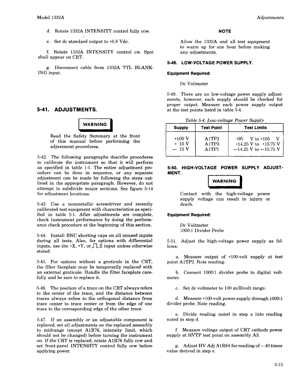
5-49. There are no low-voltage power supply adjust-
ments, however, each supply should be checked for
proper output. Measure each power supply output
at the test points listed in table 5-4.
Table
5-4.
Low-voltage Power
Supply
supply
I
Test Point
5-50. HIGH-VOLTAGE POWER SUPPLY ADJUST-
Test Limits
+lo0 V
+
15V
-
15 V
MENT.
WARNING
I
Contact with the high-voltage power
supply voltage can result in injury or
death.
AlTP2
AlTP3
AlTPl
Equipment Required:
+95 V to +lo5 V
+14.25 V to +15.75 V
-14.25 V
to -15.75 V
Dc Voltmeter
1000:l Divider Probe
5-51. Adjust the high-voltage power supply as fol-
lows:
a. Measure output of
+loo-volt supply at test
point
AlTP2. Note reading.
b.
Connect
1000:l divider probe to digital volt-
meter.
c. Set dc voltmeter to 100 millivolt range.
d. Measure
+loo-volt power supply through 1000:l
divider probe. Note reading.
e. Divide reading noted in step a into reading
noted in step d.
f. Measure voltage output of CRT cathode power
supply at HVTP test point on assembly A3.
g. Adjust HV Adj
AIR84 for reading of -40 times
value derived in step e.
Scans by ArtekMedia © 2008
 Loading...


