90 Maintenance
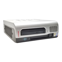
5. Remove the two 6-32x3/8 Torx screws securing the power supply to the base or expansion module
with a T-15 screwdriver (see Figure 53).
Figure 53 Screws securing power supply to base module
6. Pull the power supply handle to remove the power supply.
WARNING! The power supply can be hot.
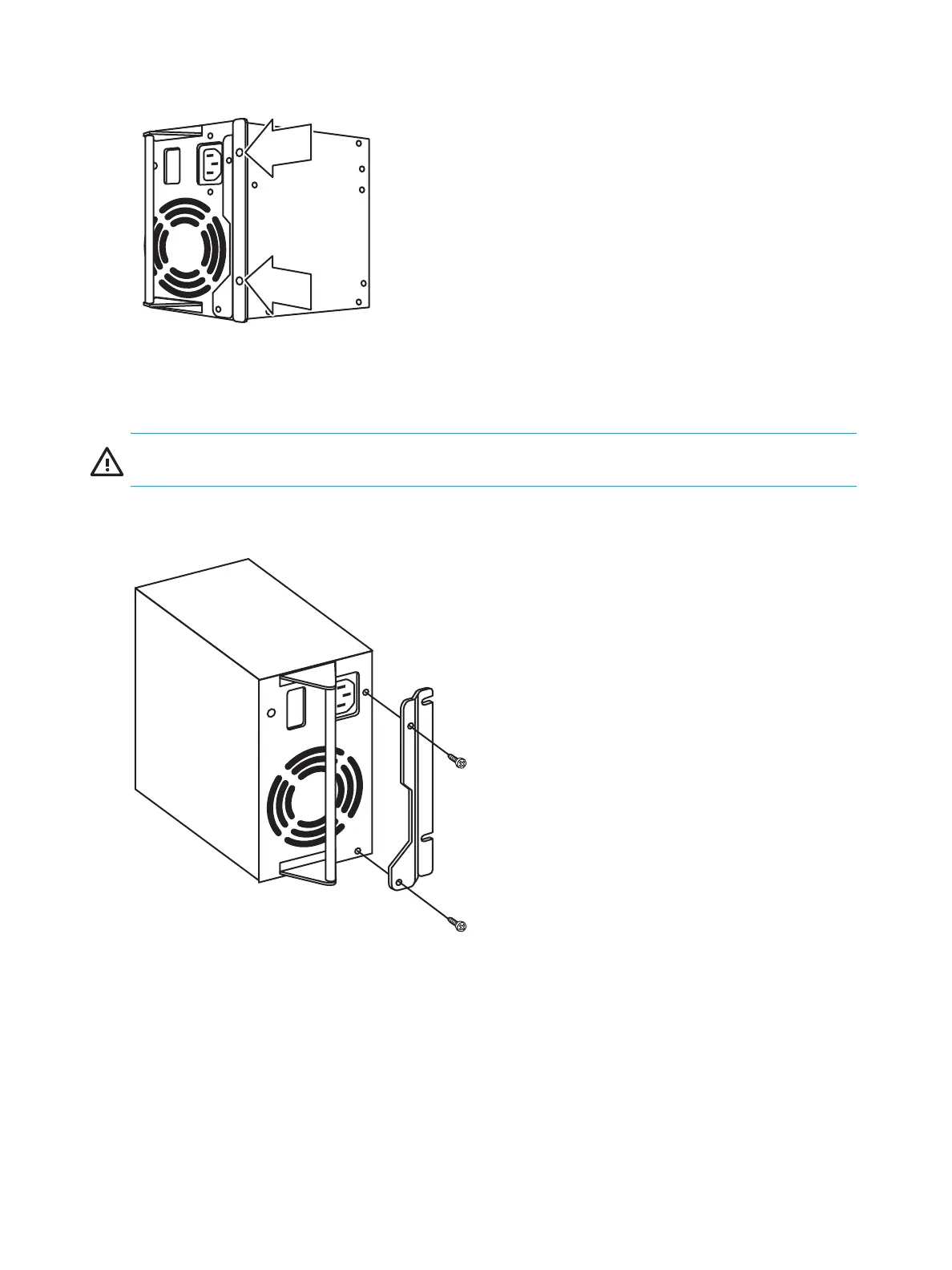
7. Remove the power supply bracket on the removed power supply by removing the two 6-32x1/4 Torx
screws securing it to the power supply (see Figure 54).
Figure 54 Removing the power supply bracket
To install the replacement power supply into the base or tape drive expansion module:
1. Attach the power supply bracket to the replacement power supply using the two 6-32x1/4 Torx
screws.
2. Slide the replacement power supply into the spot vacated by the removed power supply, and then
secure with the two 6-32x3/8 screws previously removed.
3. Connect the power cord of the replacement power supply to the desired rack power strip. The LED
should be solid green.
10466
10467

 Loading...