Product description
32 811390 Operator Manual DynaMAX 550P/560P/575P Waterjet Pump
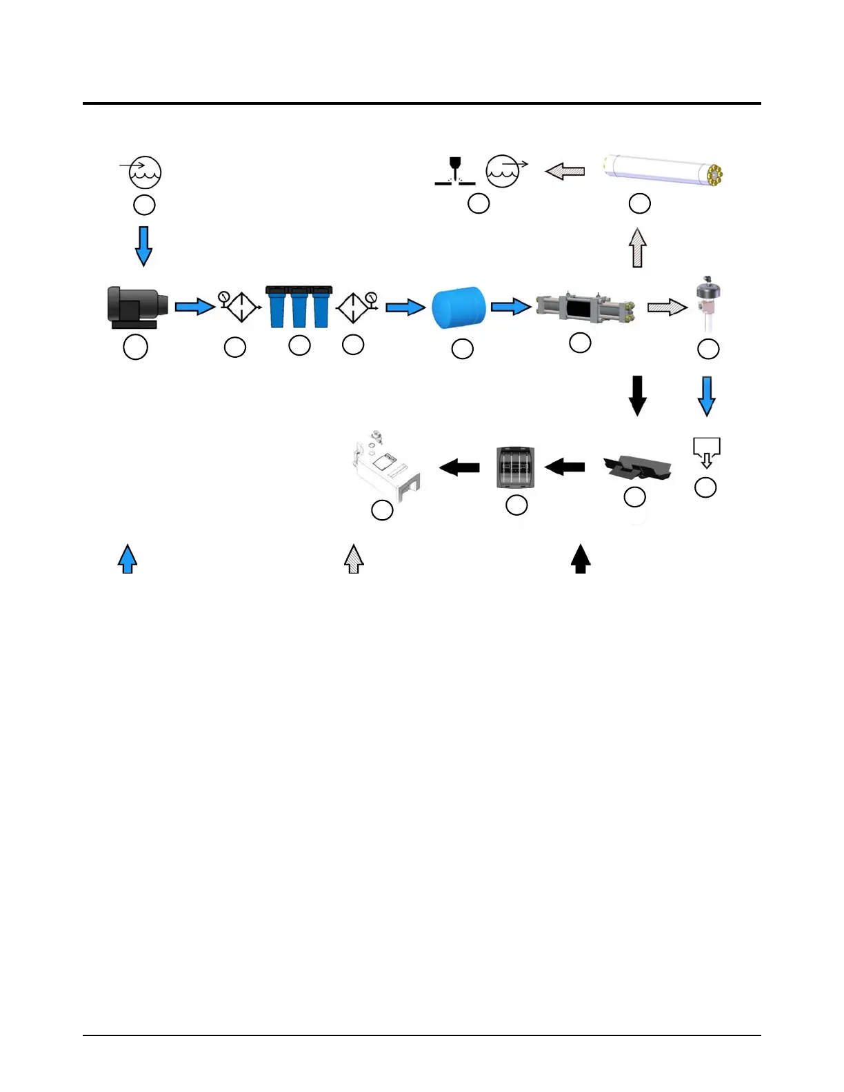
Flow of water and hydraulic fluid
These diagrams show a typical installation.
Low-pressure water High-pressure water
Seal Maintenance
Technology™
1
Utility panel: C
UTTING WATER IN
Supply water from a water softener, a reverse
osmosis system, a well, or a public utility goes
into the pump.
2
Boost pump
Increases water pressure
3
Prefilter water gauge
4
Water filters
5
Postfilter water gauge
6
Water accumulator tank
7
Intensifier
8
Attenuator
9
Utility panel: C
UTTING WATER OUT
High-pressure water goes from the intensifier
to the cutting head.
10
Bleed-down valve
11
Utility panel: W
ASTE WATER OUT
Low-pressure water goes to a drain.
12
Drip tray
13
Seal Maintenance Indicator™ (SMI)
14
Dirty water container
 Loading...