Parts/Test Point Locations 5-27
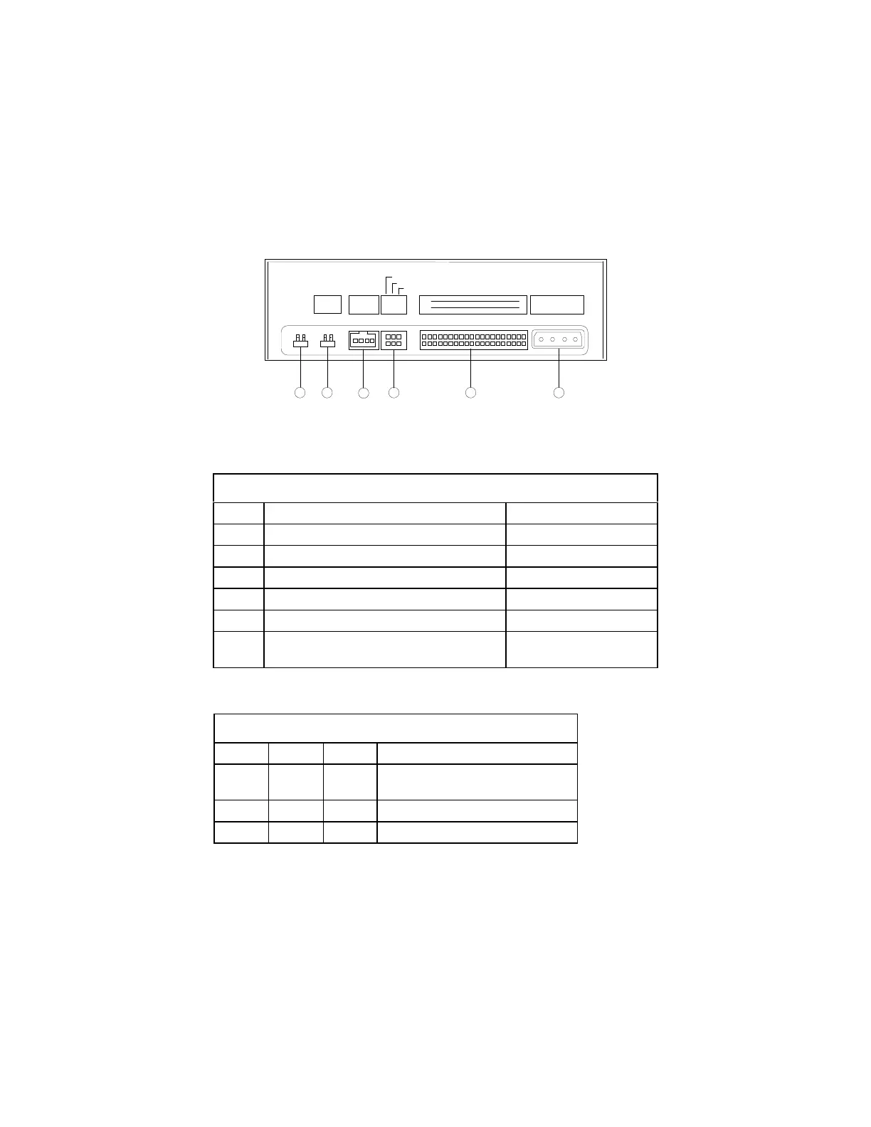
CD-ROM Drive Rear Panel Connectors and Features
R G G L
AUDIO
C S M
S L A
CABLE SELECT
SLAVE
MASTER
39
40
1
2
IDE INTERFACE
5V 12VGG
DC INPUT
5
4
3
2
1
6
AUDIO
DIGITAL
D G
Figure 5- 18 CD-ROM Rear Panel
Note:
CD-ROM drives may come with no item 5 and 6 (digital audio output
and testing jumper) connectors.
Table 5- 19 CD-ROM Drive Rear Panel Connectors and Features
Item Function Connect to…
1 Power supply connector Power supply
2 Interface connector System board (CN10)
3 Configuration jumper. See Table 5-20. --
4 Audio line out connector System board (CN15)
5 Digital audio output --
6
Testing jumper is reserved for
manufacturer internal testing purposes.
--
CD-ROM Drive Jumper Settings
Table 5-20 CD-ROM Drive Jumper Settings
CS SL MA Description
-- -- On Drive configured as a Master.
(default)
-- On -- Drive configured as a Slave.
On -- -- Cable select
 Loading...