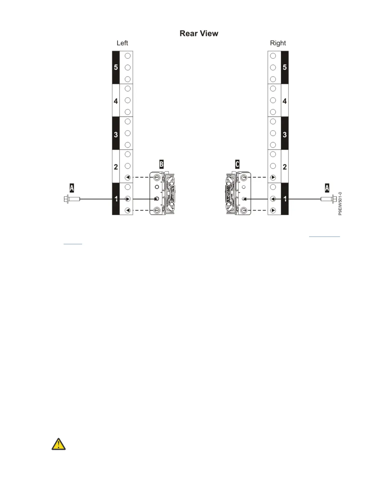
Figure 5. Attaching the slide rails at the rear of the rack
10. Attach the left slide rail (B) and right slide rail (C) with a M5x16mm screw (A) as shown in Figure 5 on
page 6. Insert and tighten each screw into the threaded slide flange hole, located in the middle hole
of the lowest EIA rack unit.
What to do next
Note: When you have nished using the installation tools, store them for future use.
Removing the shipping cover from the rear of the system chassis
You must remove the shipping cover from the rear of the system chassis.
About this task
To remove the shipping cover from the rear of the system chassis, complete the following tasks:
Procedure
1. Loosen the bolts on either end of the shipping cover.
2. Remove the shipping cover from the rear of the system.
3. If you plan to move the system later, store the shipping cover.
Removing components from the system chassis
Before you install the system into the rack, you must remove components from the chassis so that it's
less heavy and easier to lift. If you have three people available to lift the system, you must complete all of
the tasks, including the optional tasks. If you have four people to lift the system chassis, then you can
skip the optional tasks.
About this task
Attention:
6 Power Systems: Installing the IBM Power System E950 (9040-MR9)
 Loading...