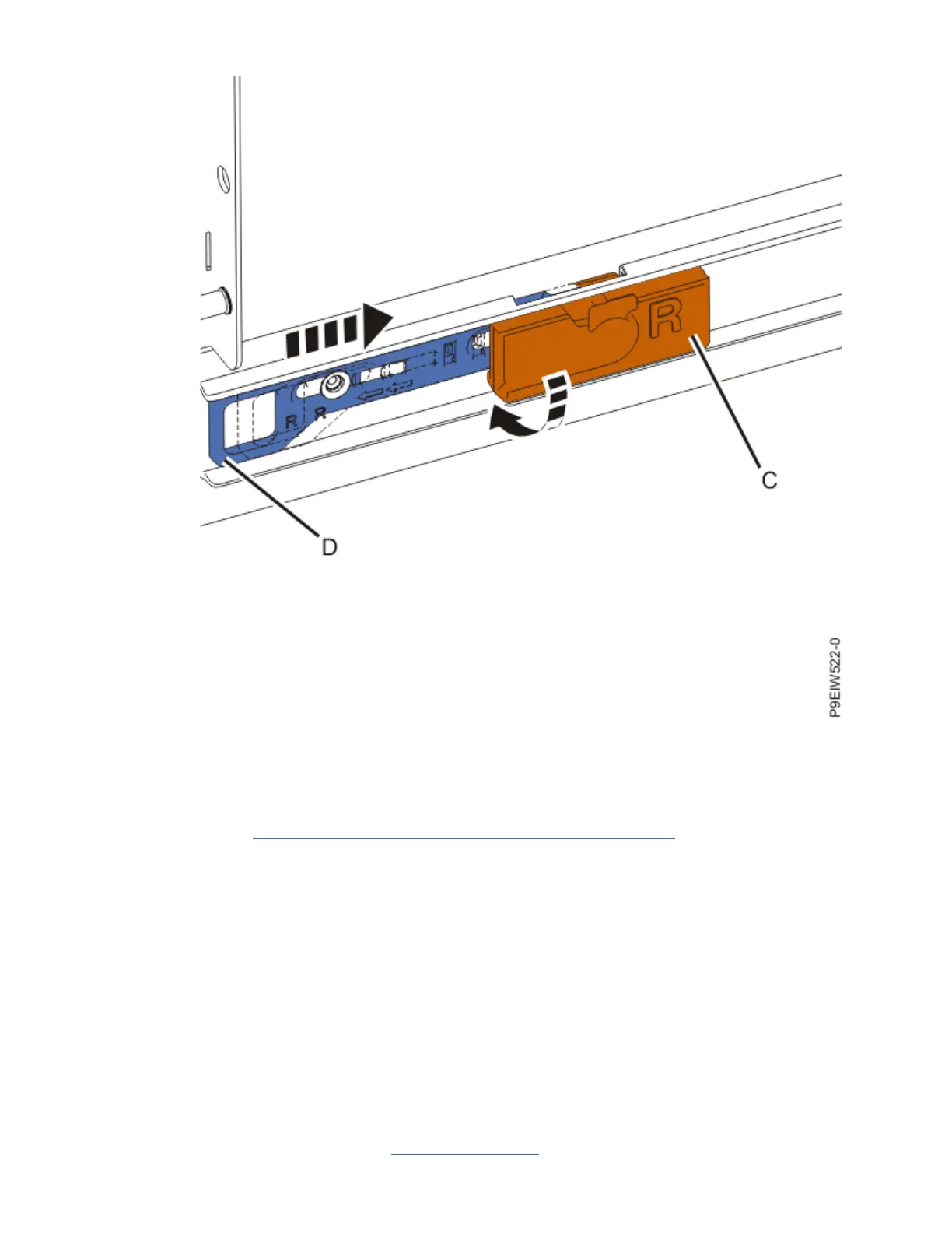
Figure 16. Releasing the blue latch
f. Repeat these steps for the L slide rail, using the clip with the side stamped L facing outward.
7. Remove the lift handles that you installed on both sides of the chassis and store them for future use.
Removal instructions are printed on each handle.
8. Continue with “Replacing components into the system chassis” on page 17.
Replacing components into the system chassis
After you have installed the chassis onto the rack rails, you must replace the components that you
removed.
Optional: Replacing the memory risers and service access cover and pushing the system into the rack
If you removed the memory risers, you must reinstall them into the system chassis.
Before you begin
To replace the memory risers, complete the following tasks:
Procedure
1. Move to the rear of the rack. To ensure that you have clearance when you push the system into the
rack, tuck the SAS cables into the empty power supply slots.
2. Move to the front of the rack. Release the latches in the middle of the rails (A) and push the system
halfway into the rack, as shown in Figure 17 on page 18.
Installing the IBM Power System E950 (9040-MR9)
17
 Loading...