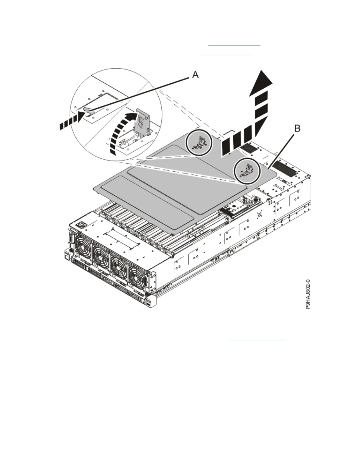
2. Remove the service access cover.
a. Push the release latches (A) in the direction shown in Figure 9 on page 11.
b. Slide the cover (B) off the system unit as shown in Figure 9 on page 11. When the front of the
service access cover has cleared the upper frame ledge, lift the cover up and off the system unit.
Figure 9. Removing the service access cover
3. Remove the memory riser.
a) Open the release latches (A) on the memory riser as shown in Figure 10 on page 12.
Open the latches to the fully upright 90-degree position.
b) Pull out the memory riser from the slot by holding onto the latches.
Installing the IBM Power System E950 (9040-MR9)
11
 Loading...