Reading the Operator Panel and System LEDs
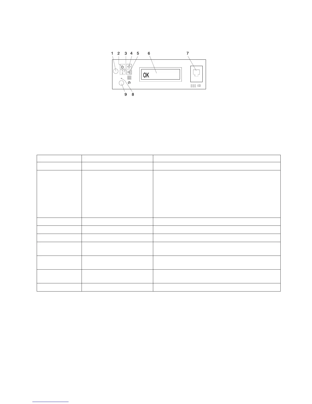
The following illustration shows the component location on the operator panel.
1 Power-On Button 6 Operator Panel Display
2 Power LED 7 (FS1) Front Serial Connector
(RJ-48 Connector)
3 Attention LED 8 Service Processor Reset Switch
(Pinhole)
4 SCSI Port Activity 9 System Reset Button
5 Ethernet Port Activity
Index Component Name Component Description
1 Power-On Button Turns the system power on and off.
2 Power LED Blinking - When connected to the power source (System is
in standby mode).
Solid - When power button has been pressed.
Note: There is approximately a 30 second transition period
from the time the power button is pressed to when the
power LED goes from blinking to on solid. During the
transition period, you may observe the blinking intervals
speed up.
3 Attention LED Normal State - LED is off.
4 SCSI Port Activity Normal State - LED is on when there is SCSI activity.
5 Ethernet Port Activity Normal State - LED is on when there is Ethernet activity.
6 Operator Panel Display Displays current status of system startup, or diagnostic
information in the event of a hardware problem.
7 Front Serial Connector (FS1) Serial port uses RJ-48 connector. Use to plug in external
devices at the front of the system unit.
8 Service Processor Reset Switch
(Pinhole)
Service Personnel Use Only
9 System Reset Button Resets the system
For more information about other system LEDs, see “Component LEDs” on page 544.
Chapter 1. Reference Information 19
 Loading...


